Ragnar
-
Posts
25 -
Joined
-
Last visited
Content Type
Profiles
Forums
Events
Articles
Marionette
Store
Everything posted by Ragnar
-
Hi, I create a beem (45x145 and 3862mm long) and creates a symbol out of it. I multiply it and later in the project I'd like to edit it and make it 45x120. I dubble click one of the beems and is given a choice what to edit. I want to edit the extrusion so I choose "3D component". In the Object info palette it says that the symbol is ∆X: 1, ∆Y: 77, Extr: 3. If I grab a corner and resize it's the same. What is this and how do I make it show the same values as in the design layer?
-
I am sure this exist, I just cant find it, nor an answer in the forum. Next to my window, I'd like to add a tag that states what type of window it is. Typically it would say "11/13 Bipart" or "10/20 fixed". I imagine there is such a tool?! Best regards
-
OMG !!! Thank you!
-
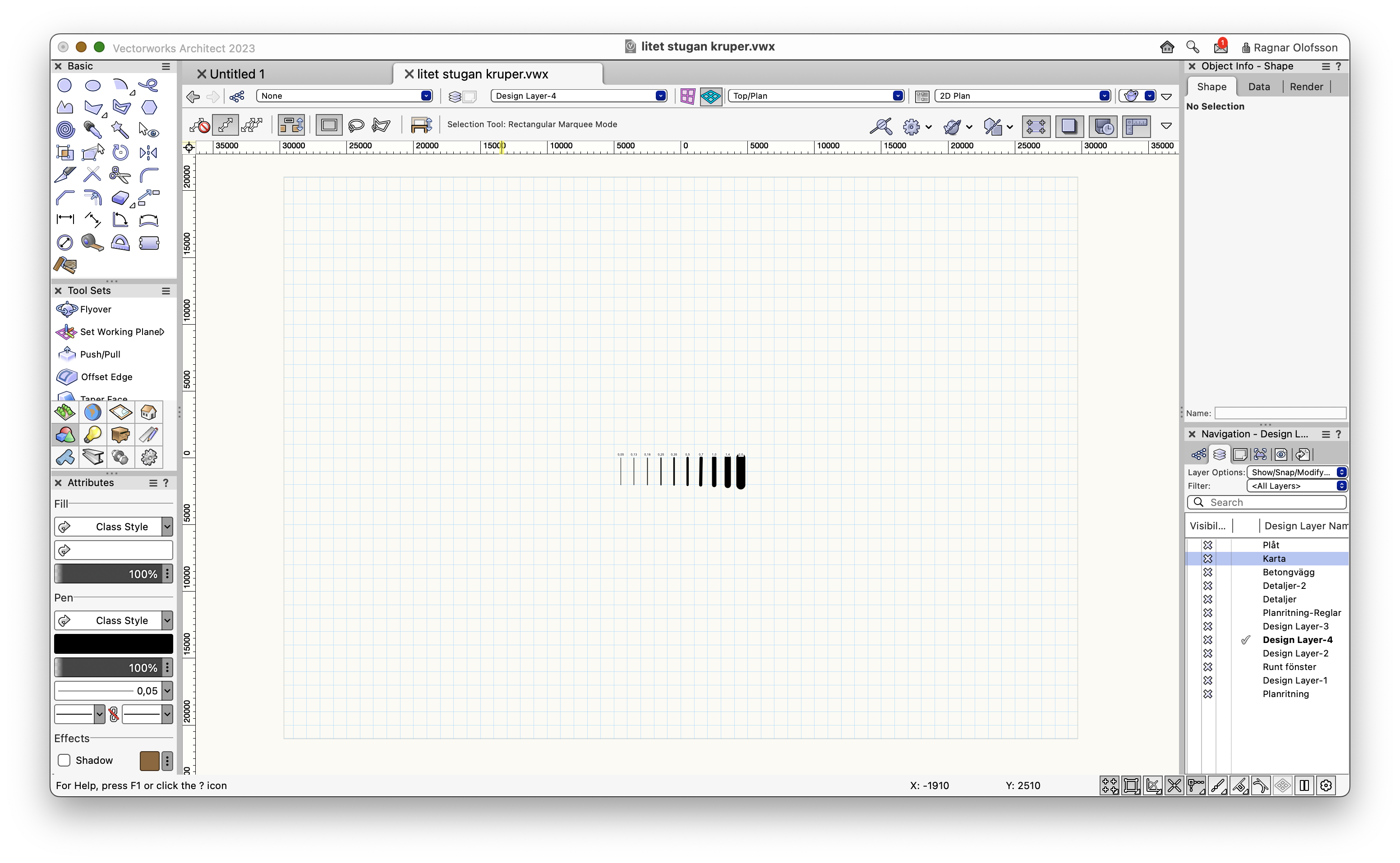
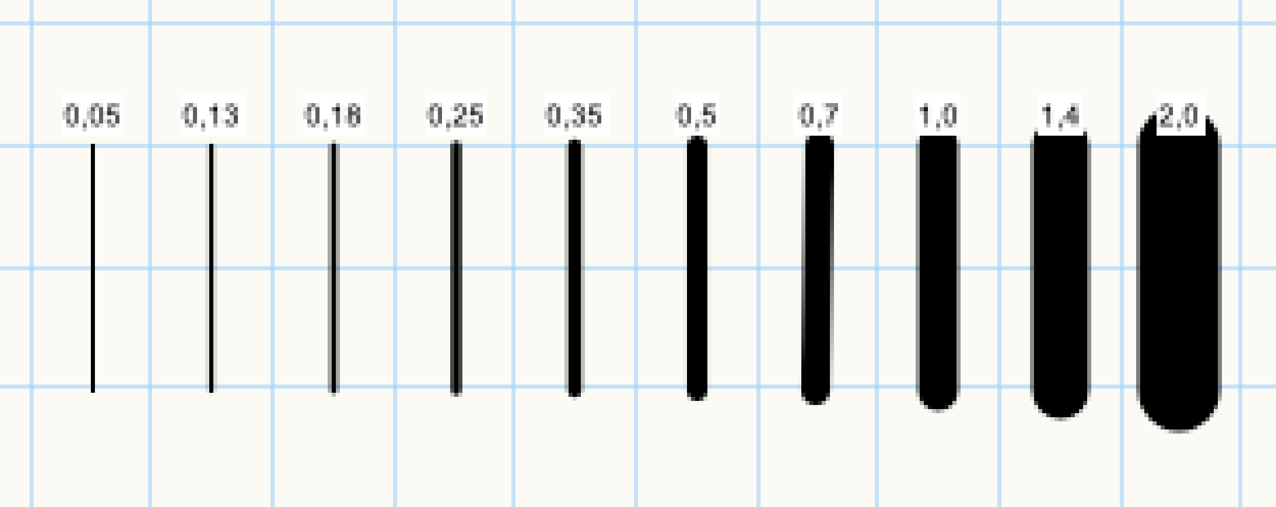
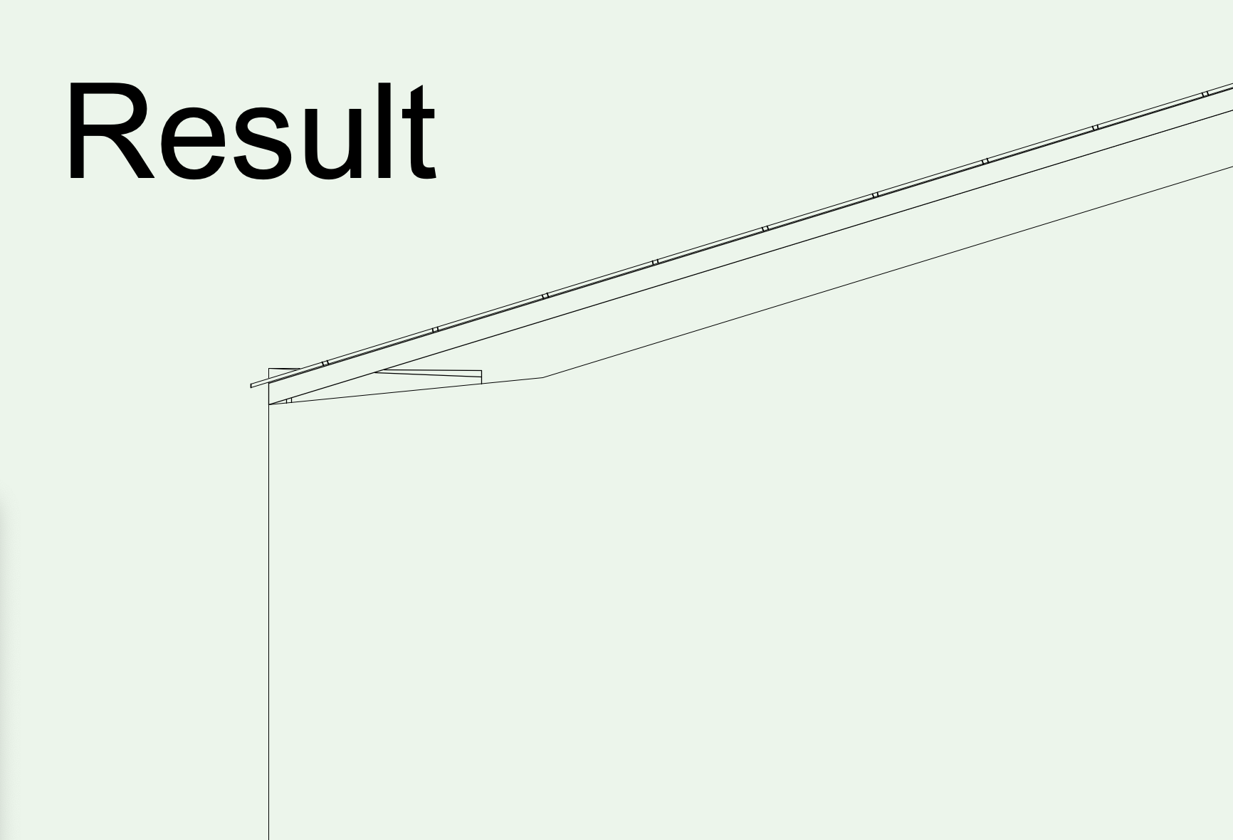
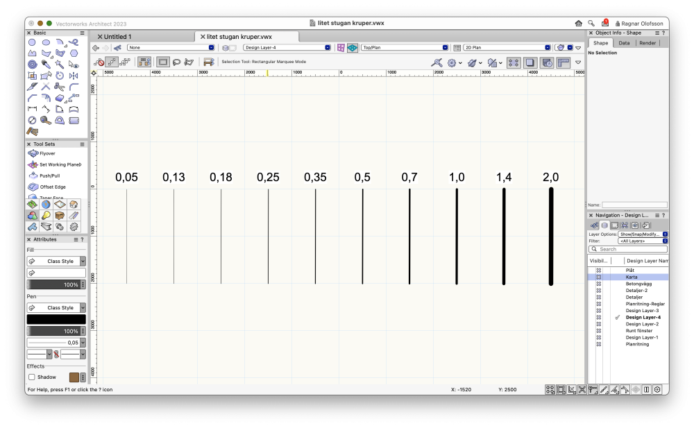
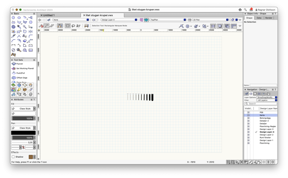
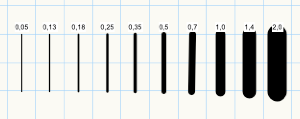
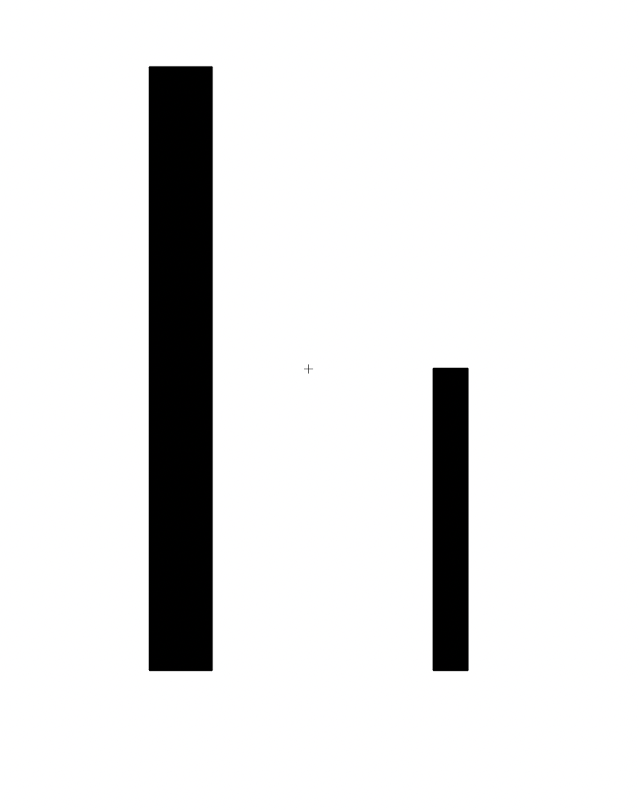
I have been pondering this for quite some time. Thin lines stay thin and thick lines become obese, when zooming out. Is there a setting? Here is the facts. The grid is set to 1 000 mm. Lines are 2 000 mm. Drawing them they all look OK compared to each other. Zooming out however... Picture nr 1. "Normal" Picture nr 2. Zoomed out. The thicker lines swells. Picture nr 3. I enlarged picture nr 2 What can I do to not have this problem?
-
Hi! I am using a Mac Book Air M1 2021, and it is fine as long as I am not rendering 3D. Then it doesn't take long until my patience run out. Will a basic Mac Book Pro do the trick?
-
How did you solve this? I have the same problem and I can't find the On switch, so to speek.
-
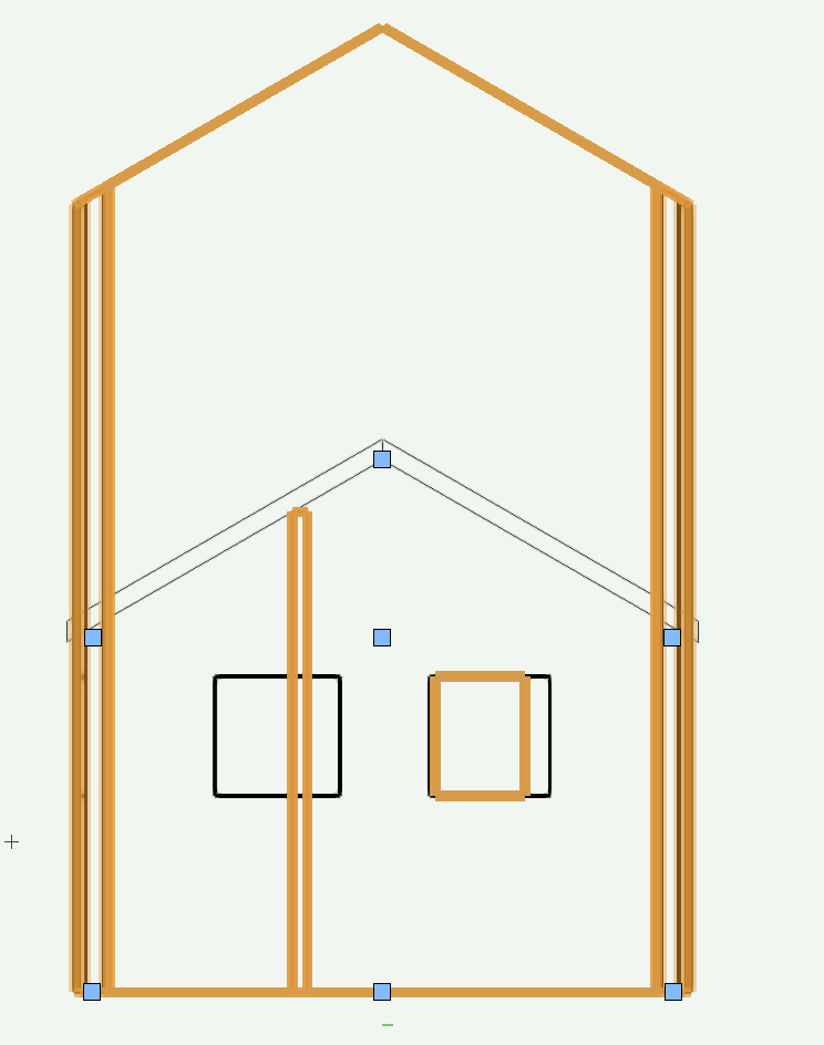
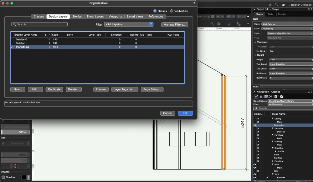
Even more confused when I dubble click the wall...
-
I find this bizare. No layer elevation. The wall measures 5247 but is declared as 2361. I did a "Fit walls to object" to shorten the walls but Nope. What am I doing wrong?
-
Thanks, It was resolved with a lot of waiting for the computer to calculate. 😄 It was a DWG.
-
So, I bought a 3D map file over a building site. As it happens the site is located in an overlap of two scanning areas, and too many measure points have been presented to me. Up to 50 points per square meter. The file gets super heavy! Any tip on how to delete some of those at the same height and in near proximity of each other? Alternatively, is there a way to see one "altitude" at the time?

-
Why has my section viewports no or few details?
Ragnar replied to Ragnar's question in Troubleshooting
Fantastic!!!! Advanced Properties 'Seperate Cross Section' sent me leaps ahead. Thank you! -
Why has my section viewports no or few details?
Ragnar replied to Ragnar's question in Troubleshooting
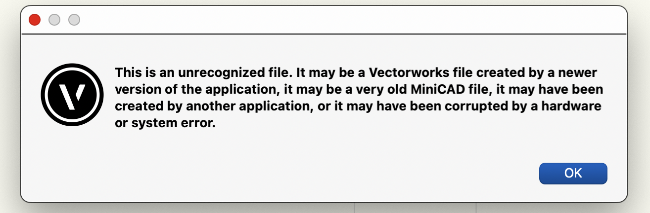
AlanW. I can'n open your file. I am running VW2021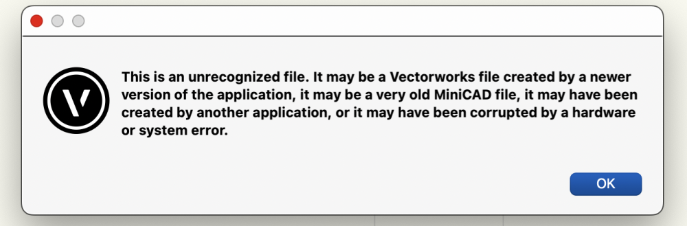
-
Why has my section viewports no or few details?
Ragnar replied to Ragnar's question in Troubleshooting
4 hours more of trial and error. Nothing good comes out of it. I attaches a QuickTime movie if anyone has the energy to look 🫣 Skärminspelning 2022-09-13 kl. 14.27.11.mov -
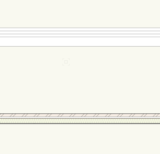
To simplify I have made just two walls. One is "Exterior Veneer Wall" and one I have created my self. I'll attach two images. One from Top/Plane view and one of the section viewport. Actually, I'll add one more for detail. But why do my viewport look so useless?
-
I can't change line attributes - because its a symbol
Ragnar replied to Ragnar's question in Troubleshooting
Thank you zoomer. I think this did the trick, together with choosing one Class and one Layer at a time. 🙏🏼 -
I can't change line attributes - because its a symbol
Ragnar replied to Ragnar's question in Troubleshooting
But there are thousands!! -
Is it because it's not a line? I imported a map document in .dwg. Ended up with 27 layers. I need to change the attributes but it seams unchangeable. What steps do I need to take? Oh! But wait. All lines are symbols 😳. Can I change them into lines, polygon or something of that kind.
-
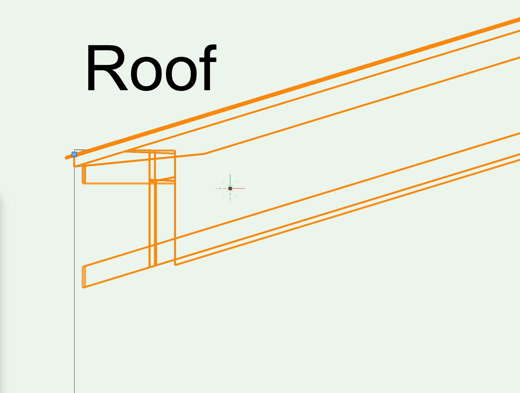
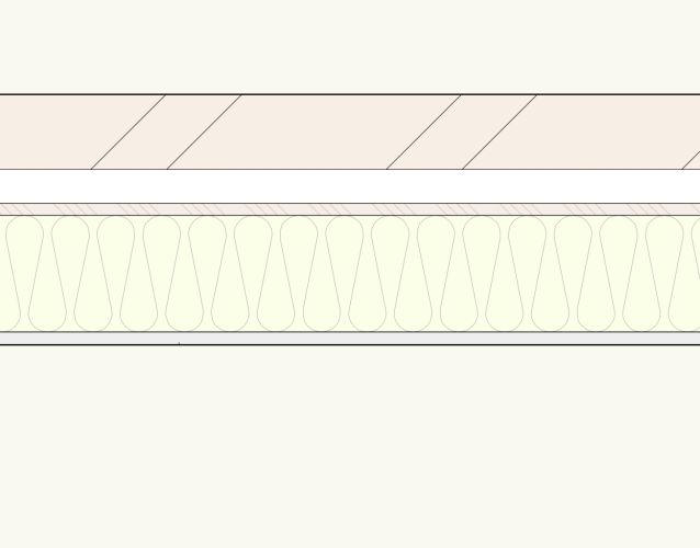
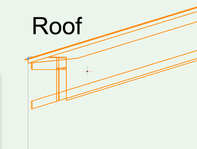
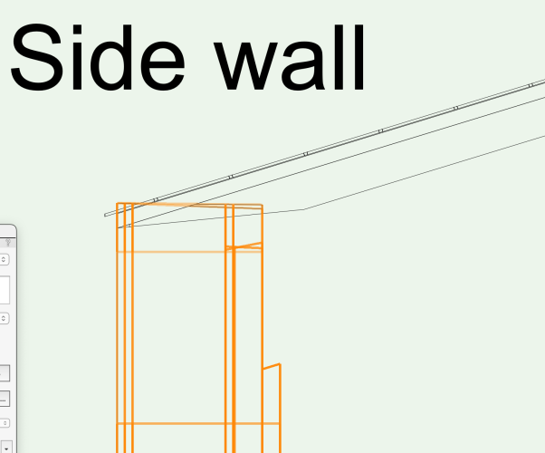
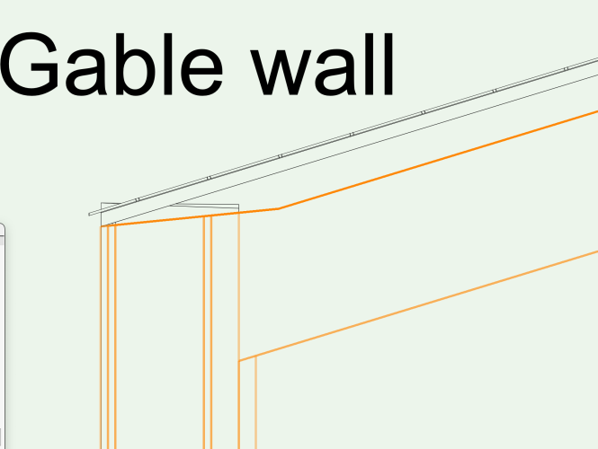
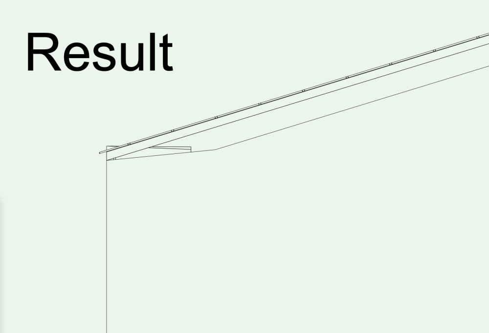
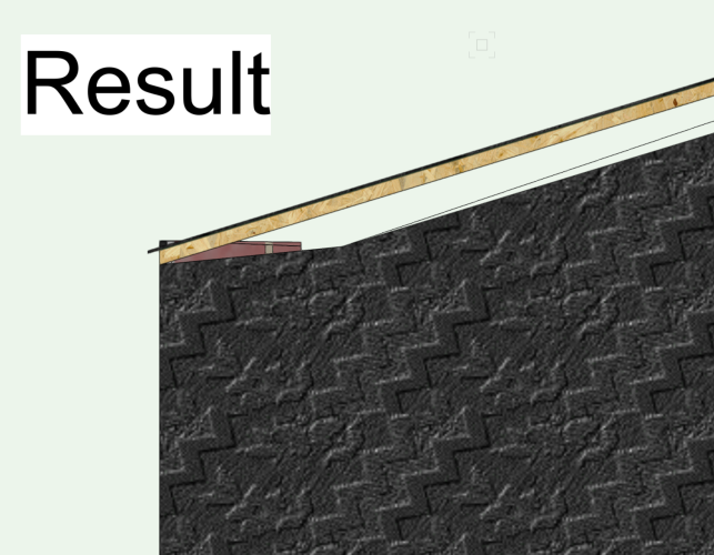
Hi! I have been working around this problem for years and I am sure there is a reasonable explanation and fix to this. I have a simple wall and a simple roof. Edited with the right components. Then, when I want to "Fit Walls to Objects" I don't get quite the result I was hoping for. I have been trying to alter the "Wall top embedding depth" but it makes it worse. The result is a gap between the gable wall and roof. When altering the embedding depth the top will look fine but the side vill stick out of the roof.
-
I will give this a try as well! Thanks!
-
This worked perfectly! Thanks
-
Hi, I might be aksing the wrong forum. In that case, sorry. Please direct me to the right place. I would like to visualize my building in the garden which has a gentle slope and some small hills. Is there a way to add this? Like a lawn. Without having "Landscape". Tanks. /Ragnar Olofsson
-
Your answers has been most helpful. Thank you! I now would like to soften the edges of the holes. What tool or steps should I use for this? Thank you again. Ragnar
-
I am designing a board 1200x2400mm with 325 holes with a diameter om 20 mm and a vertical and horisontal distance of 96 mm. Making one hole in the board is not a problem, using the "Push/pull tool:sub face mode". But making it 325 times...! I don't seam to be able to copy/paste a hole. Nore can I select more than one circle at the time to extrude. Any suggestions?
-
Thanks for your help. I do appreciate it!!
-
Hi, this is probably a simple question but I just can't sort it out. I have several Roof faces that I want to Connect/Combine. This works great until I change one of the roof faces with the Push/Pull tool. Then they are no loger selectable with the Connect/Combine tool! I guess it turned into an object or such? Is there any way to remake it into a virgin roof face again? Without deleting and do it over again! If it's of importance, I use VW 2014 Architect on a iMac.