


line-weight
-
Posts
3,755 -
Joined
-
Last visited
Content Type
Profiles
Forums
Events
Articles
Marionette
Store
Posts posted by line-weight
-
-
Ho hum. I guess it's a bug in 2018 that will never be fixed, then.
Time for me to waste yet more productive time making a workaround.
It seems the same applies to subdivision surfaces.
Eurghh!!

-
Yes it's possible, and normal.
It will cause you problems if you want to view two layers at the same time, and they are at different scales though.
There's something called 'unified view' and I've never quite understood what it actually does.
I find the concept of different design layers having different scales a bit confusing. What it really means is the scale that you view them at - which becomes relevant for things like line thicknesses.
These days I have nearly all my layers set at 1:1 because otherwise I have problems in 3d. Scale only comes into play when I make a viewport on a sheet layer.
-
19 minutes ago, zoomer said:
Du hast VW 2018 SP6.
Hab ich eben ausprobiert - geht hier auch.
Aber Du hast eine Perspektivische 3D Ansicht gewählt - da geht's nicht,
bzw. nur teilweise.
Das liegt wohl daran dass das 2018 Auswahlwerkzeug, bzw. dessen Rahmen,
nicht mit der Perspektive klar kommt. Es deckt sich nicht mit dem was Du siehst.
Versuch mal mit einem grösseren Marquee, auch von weit ausserhalb,
auszuwählen. Manchmal findet es einen Punkt 😉
Wenn Du von der Perspektive auf Orthogonal umschaltest sollte es gehen.
In VW 2019 wurde das wohl gefixt.
Auch in der Perspektive aktivieren sich die Punkte sofort, sobald sie der
Rahmen tangiert.
Übrigens, Für VW 2018 wird es kein weiteres SP mehr geben.
Luckily I know enough German to understand this!
You're right, changing projection to orthogonal solves it.
Danke sehr!
-
-
6 minutes ago, zoomer said:
Are you sure it is a Mesh ?
😀
That's what it says in the OIP!
Tried with rectangle>pushpull>CMD-ALT-R as you suggest ... same happens.
-
I've tried the selection tool in all 3 modes.
Class/Layer are active.
If I select a 2d object, the blue handles appear. But not on the mesh.
I'm using VW2018.
-
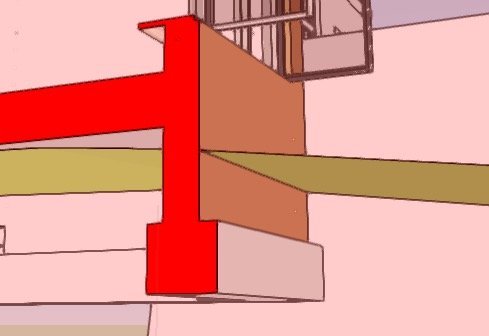
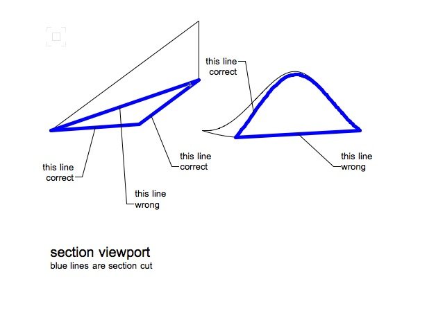
Here's what the subtraction looks like in section viewport:
The extrude was subtracted from the DTM on the left (the one on the right is unaltered)
The 'hole' in the ground is where I subtracted the extrude. You can see it's rendering it as a surface instead of a solid now. Which in a way is fine by me...
But... it is not showing the section through the surface correctly... it seems to be doing the same thing as I've described in this thread:
-
16 minutes ago, zoomer said:
I think I had seen that in some webinars.
Could it be just the typical error of not having both objects on the active Layer ?
Ah - you are right.
So, it has subtracted a simple extrude from the DTM, and the object I am left with is a solid subtraction. So it doesn't have the options of displaying contours and so on.
The DTM is still 'inside' the subtraction, at least, so I could still go in there and edit it.
Not ideal though. I would still have to subtract a lot of separate below-ground elements to make it correct.
-
2 minutes ago, zoomer said:
You don't have to double click to go into an "Edit Mode"
You will need that only to manipulate repair on a single separate Polygon basis.
(*) See Meshes as already being in an "Edit Mode".
Don't even Select them before.
Just start by selecting their desired Vertices by a Marquee Selection.
This will activate your selected Vertices and you can drag them around.
((*) which is quite error prone to destroy them accidentally if you have any Meshes
in your Drawing and doing standard Marquee Selection for standard Objects)
Thanks @zoomer - but this doesn't work for me. With the mesh object non-selected, making a marquee around one of its vertices does nothing - no vertices are selected.
-
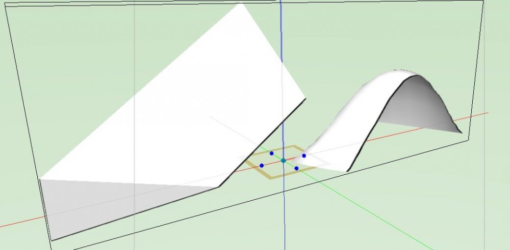
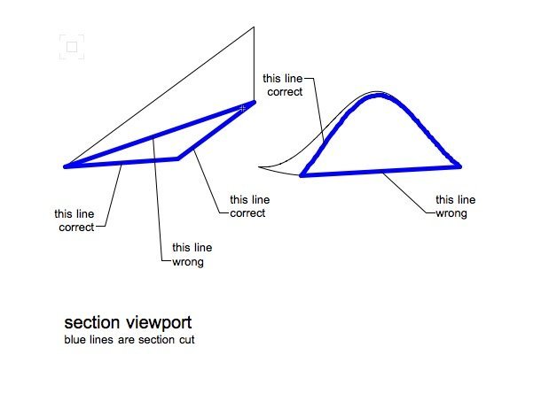
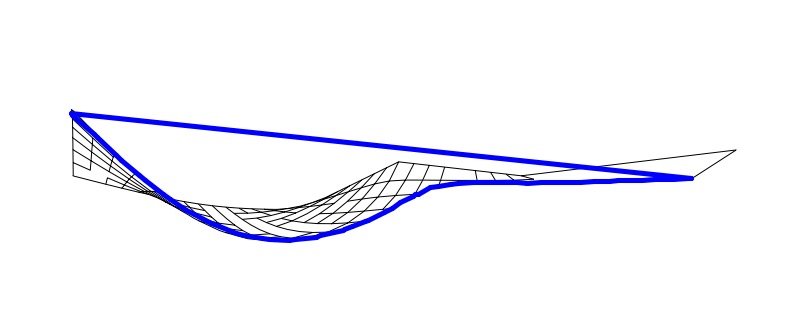
The top image shows two surfaces, sectioned using the clip cube. The one on the left is a mesh; the one on the right is a NURBS surface. In the OpenGL clip cube, the section is correct.
However, in a section viewport, they are not sectioned correctly, with an extra line joining the two ends of the line that represents the section through the surface. This is shown in the second image.
I have attached the file.
-
I can't seem to edit mesh objects in the way that is shown in he video below. I want to move vertices so that all of the polygons that share that vertex are adjusted.
If I double click on the object I am taken into a group of 3d polygons which I can only modify individually. In other words moving a vertex only affects one 3d polygon, and it becomes detached from the others.
The same happens if I use 'Move: vertex only' in the OIP, manually typing a different z value for a single vertex. It only affects one polygon.
-
8 hours ago, Patrick Fritsch said:
Yo! VW developers...Either fix the tool or take it out as it's a useless piece of junk...NO results since this was submitted in 2016 and probably before...sad! Oh but don't tell me we have point clouds instead, more junk bling bling!
In the meantime... you might find this discussion useful:
-
6 hours ago, markdd said:
Could you use the Extract Surface tool on the site model serfaces, add them together with the Add solids command and then Shell tool the result?
Maybe... but ideally whatever the resultant object is, should be easy to edit.
-
7 hours ago, Boh said:
Haven't tried it but what about stacked section viewports?
One just for the DTM and the other for your bldg model. With two viewports you could set the attributes of each differently in the "Advanced Properties".
I don't think that would work unless I did some intricate cropping of the viewport that had the DTM, because the DTM section would have to sit 'behind' the section of the building and in 'front' of the elevational linework of stuff beyond the cut plane.
I guess there could be one VP with everything, then in front of that one that only shows the cut plane through the model.
Would prefer to avoid stacked viewports if possible though.
-
VW doesn't seem to want to let me do a solid subtraction including the DTM (selecting it and a simple extrude leaves the option greyed out in the menu)
-
4 minutes ago, Kevin Allen said:
Not my specialty, but can't you do a solid subtraction out of the DTM?
I've sort of assumed that wouldn't work with a DTM but maybe i should try...
Even if it works though...if you've got a lot of walls and foundations and other below-ground detail, it's going to be a rather fiddly process and hard to edit if you subsequently change the position of eg a wall.
-
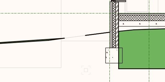
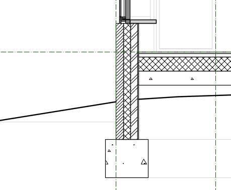
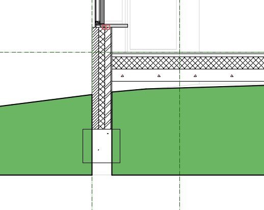
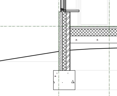
In essence, I want to end up with a section viewport that shows something like this:
The green represents the 'ground', which of course the bottom of any wall and its foundation is going to be buried in.
In actual fact what I'm really interested in is the solid line that represents the surface of the ground: I want this to be generated from what I model in 3d. So, I'd also settle for something like this:
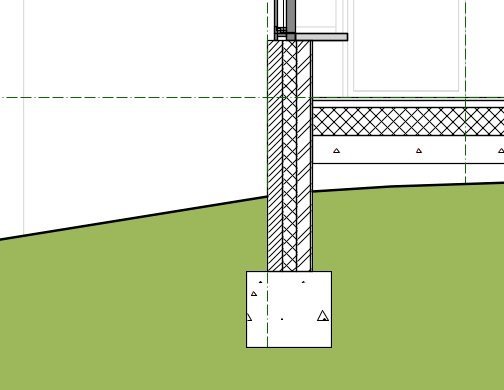
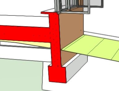
I've been trying to do this using site model objects to model the ground surface and that works fine at least looking at it in OpenGL, set to view as a mesh surface with no 'skirt' (it's helpful to view be able to view the model with the ground as a surface, rather than a solid block, because then I can still see what's going on below ground). Here's what it looks like in OpenGL:

But in a section viewport I get this:
Which, of course, is not what I want. So, is there any way to:
(a) have the section viewport only show the ground surface of the site model object (not the 'skirt' sides and bottom)?
(b) Somehow wrap the site model around the geometry of the wall and foundation (so it looks like my first image at the top of this post)?
(c) Use some other kind of 3d object to achieve what I want?
-
^ I have replicated the second issue in a 'clean' file and posted here:
-
(This is VW2018)
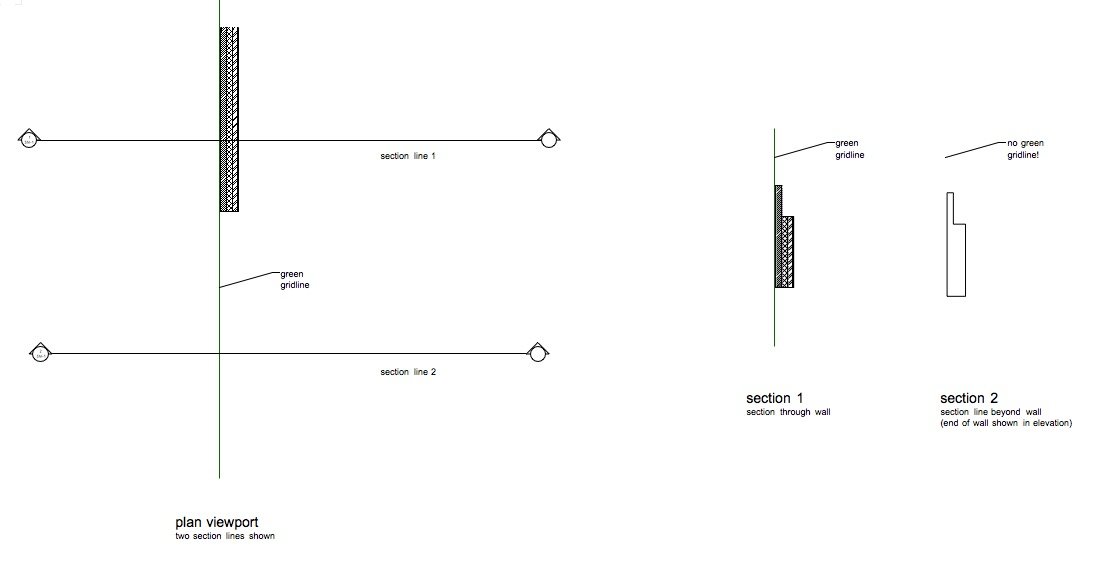
The screenshot is from the attached file.
The model contains two objects: a wall object and a polygon object ('green gridline').
Section one cuts through the wall and the green gridline, and both show up as expected.
Section 2 cuts only through the green gridline. The wall shows in the background in elevation as expected but the green gridline does not appear at all. Why is this?
(File contains 2 saved views so you can look at the model and the sheet layer)

-
The point of the affinity apps is that they are built from scratch with a focus on the UI. They are cheaper than photoshop but also don't have the legacy of years of iterations on a longstanding system. VW is cheaper than Revit, yes, but it's bogged down in years of legacy function and has a terrible UI. There's no 'clean start' in the design of VW.
-
 2
2
-
-
5 hours ago, digitalcarbon said:
just had this in front of me for an advertisement...
this is not going to help anyone...it will start out as saving time but then we will fill up our time with other things and soon our lives will be choked...again.
Depends what the other things are - are they things that are more enjoyable or not. In theory, technology means that we can replace tedious labour with rewarding pursuits - of course, history so far has shown that this is not necessarily what happens, but some would say that the blame for (or solution to) that can be found in the way we organise our societies.
On the choked motorways analogy - the solution is organise better: public transport! Then we have a mode of getting around that potentially functions better the more people use it, rather than what happens with private cars which is the opposite.
-
5 hours ago, mjm said:
@line-weight: please elaborate on that workflow when you have a sec. I am interested.
I've found, at least for the kind of buildings that I do, that it's really a pain trying to build a model that also 'works' in top/plan view. All the stuff that I was having to do to get it to be correct in top/plan view was hindering me in having a model that I could edit fluently; it was just unpleasant trying to use it as part of a design process because there were certain things that I had treat specially in order not to break other stuff, and certain simple changes were just unduly tedious.
And I still wasn't getting floorplans, in top/plan view that I was happy sending out as finished drawings. This was partly due to the patching-up I was having to do in annotations - it was just too difficult to get a clean output.
So I decided to try a different strategy: the model is built in a way that makes sense in 3d rather than a way that forces top/plan view to produce something like what I want. This means quite a bit of stuff is solid-modelled rather than made with VW tools. Some stuff is built as wall objects and so on, but I'm now more free to use, say, wall objects where that makes things easier, and make other bits of walls from directly modelled objects where it doesn't.
Then the plan is simply a horizontal section viewport, sliced at the cutting plane height I want. This throws up a few small problems, which still have to be fixed in annotations, but I think fewer than when I was trying to do stuff in top/plan. There a few things - like door swing lines - that I have to draw on manually.
Editing the plan becomes a little messy - I still use top/plan for this, where it makes sense, but much of my editing and draughting is now done in a 3d openGL view instead.
I'm sure there are other types of project where this strategy wouldn't make things easier. For what I do which is smaller architectural projects with lots of one-off stuff and often involving old buildings and things like roofspaces, I think it suits me better. I'm currently trialing it on a couple of small projects, through to construction drawings. So I haven't tested it right the way through the process yet but so far it seems fairly promising. I was thinking that once I've reached the end of one of those projects, I might do a thread on here and post a version of the drawing file so that people can see what they think. Personally I think VW should head more in the direction of horizontal section concept for floorplans and that top/plan should gradually be brushed under the carpet. Others may disagree!
-
1
-
-
Was quite hopeful about the 'gridtangle' concept but running into some issues now that I am trying to implement it in a real project.
The first is that they only properly work with non-merged type sections, because with a merged section you have to assign a linetype for sectioned objects that applies globally - so where the gridtangles are sectioned, they show up as solid lines and there's no way I can see to override this so they show up as whatever linetype you want for your gridlines. For merged type sections it looks like you'd have to use overlaid viewports, which kind of defeats the purpose somewhat.
The second is that even in non-merged sections they seem to show up unreliably. In some viewports they work as expected and in some they just don't show as a sectioned plane at all. They seem to disappear when I move the line of teh section cut for example. While it's possible there's something I am doing that I haven't thought of, I've spent the last hour or so trying to work it out without any success.
-
My current favourite approach is to ignore top/plan completely, and my plans are generated as horizontal sections.
-
2
-


Why is object showing in one section but not the other?
in Wishes Granted / Issues Resolved
Posted
Further testing suggests this happens when the section line doesn't pass through any non-planar objects. So is this a bug?