line-weight
-
Posts
3,755 -
Joined
-
Last visited
Content Type
Profiles
Forums
Events
Articles
Marionette
Store
Everything posted by line-weight
-

How to set an even or smooth gradient on a nurbs curve
line-weight replied to line-weight's topic in General Discussion
Unfortunately it's not following a constant radius ... it's following a path that I will trace off a survey plan. So I don't think a sweep would work. I don't think a loft would work either, for the same reason - the true line of the curve can't be interpolated just from 3 points. -
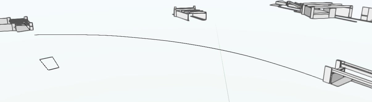
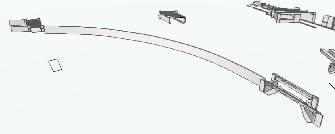
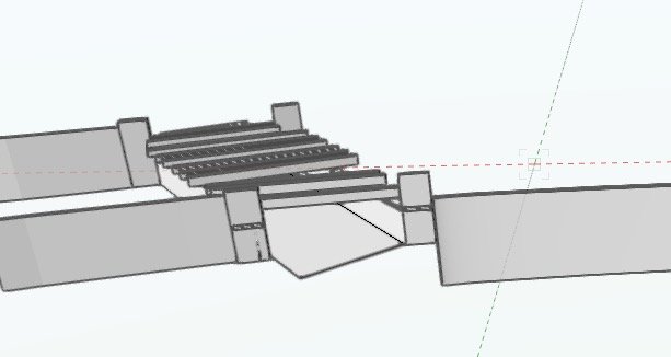
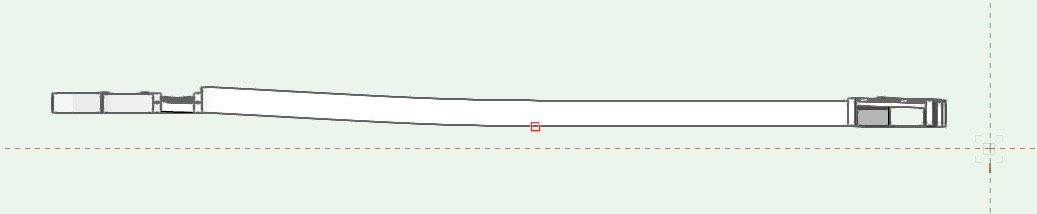
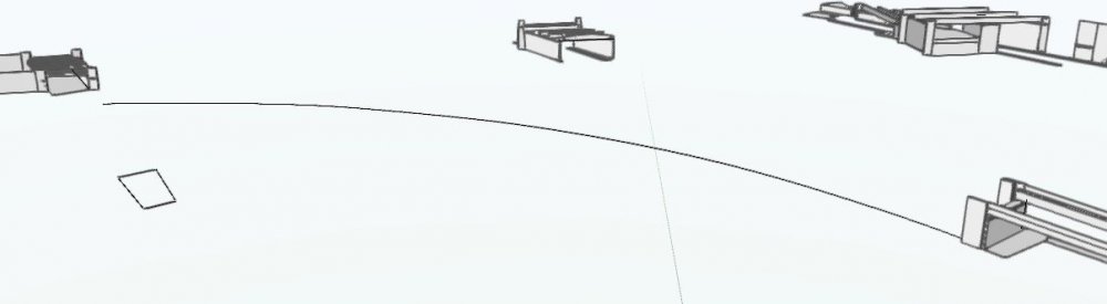
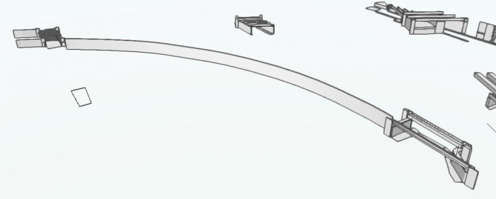
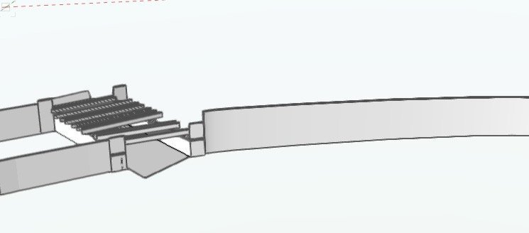
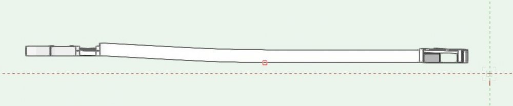
Easiest to explain this by providing an example of what I'm trying to do. I've got two bridges, and I want to draw the wall of a viaduct that runs on a curve between them. I know the path of the wall in plan, so I draw the NURBS curve, all on the X-Y plane: Then I use this NURBS curve as the path for an Extrude-along-path, to create the wall: That's fine except that the bridge on the left is at a higher level than the bridge on the right, so the base of the wall where it meets the bridge on the left is too low: I can fix this by editing that NURBS curve, and raising the Z value of some of its vertices towards that end: And that in principle gives me what I want. However - ideally what I want is a smooth gradient from one end of the curved wall to the other. That's not what I've got, as can be seen looking at the wall in orthogonal elevation: Obviously I can improve that, just by fiddling manually with the Z-values of each of the vertices of the path, but that's rather tedious and I'll only get it as good as I can manage by eye. Is there some way to draw that NURBS curve, such that I can make it follow a constant gradient from one end to the other?

-
The documentation for the Extrude Along Path command misses out lots of info, as far as I can see. http://app-help.vectorworks.net/2018/eng/VW2018_Guide/Objects_edit2/Extrude_Along_Path.htm I'm always wary of this tool, because I never quite understand what it's doing. Sometimes I'll use it and it'll do what I want, sometimes it won't. Here are some basic questions that don't seem to answered in the VW help guides. 1. In what plane can I draw the profile object? Does it matter? Sometimes it only seems to work if I draw it in a top-plan view, sometimes I can draw it in some 3d plane and it works, sometimes it doesn't. 2. Does it matter where I draw the profile object, relative to where I draw the path? (Through trial and error, the answer seems to be 'no') 3. Which point on the profile object follows the path object? (Through trial and error, it seems to be the centre of it. And the only way to change this is to edit the profile after creating the EAP object)
-
Controlling visibility using data visualisation
line-weight replied to line-weight's topic in General Discussion
Would it be feasible to create a script that could interpret a class name, and then use it to apply visibility settings to a viewport? So for example if the class name is 1870-2004 (or some other standardised naming), the script can take the requested view date (let's say it's 1950), find whether it is between 1870 and 2004, and if so, set that class to be visible in a selected viewport? -
Controlling visibility using data visualisation
line-weight replied to line-weight's topic in General Discussion
I think that having saved views set up could potentially work, if those visibility settings could flow through to a sheet layer viewport, although I don't really see how that could happen. A downside of this approach is (I think)that I'd have to re-perform the custom selection process, and redefine the relevant saved views, each time I added a new object to the model. Yes that's a good idea, a way to get around the limited filtering abilities of DV. I think this could work well, as long as the method of setting line/fill to none doesn't have any unexpected side effects. -
Controlling visibility using data visualisation
line-weight replied to line-weight's topic in General Discussion
Yes, I think it maybe works (see question 1 in my original post) to set pen/fill to 'none'. But even if that works - it's not (as far as I can see) then possible to apply this to objects outside of a data range. I can apply it to anything built before a certain date, or demolished after a certain date, but not both. See question 2 in my original post. Hence @Boh's suggestion involving the 'custom selection' function, which allows you to select something that satisfies one condition AND satisfies another condition. -
Controlling visibility using data visualisation
line-weight replied to line-weight's topic in General Discussion
I'm not that bothered about my class system remaining intact for this project. I could do it by class or layer - my preference is usually to keep number of layers to a minimum, which is one reason to do it by class, also, classes are much more flexible when you are grouping things (I can have several classes within a group and make some of them visible/not visible, same is not possible with layers) But whether it's class or layer the basic issue is ending up with hundreds of them, which then have to be manually selected for visibility for each viewport. It's doable, just a bit tedious. -
Controlling visibility using data visualisation
line-weight replied to line-weight's topic in General Discussion
Thanks, yes I would be interested to hear how that would work. Would it be possible to apply it to viewports though, or just what is visible whilst viewing the design layers? -
I agree completely @Amorphous - Julian.
-
Controlling visibility using data visualisation
line-weight replied to line-weight's topic in General Discussion
Ah yes, I know what you mean, I have exactly the same sometimes. -
Controlling visibility using data visualisation
line-weight replied to line-weight's topic in General Discussion
you lost me after you mentioned your 'usual versioning' - what's that? -
Controlling visibility using data visualisation
line-weight replied to line-weight's topic in General Discussion
Yes, good thinking to exploit the capability of the "custom selection" command. That would avoid having to manually select which buildings show up in which views. It wouldn't automatically change what's visible in each view if I made changes (say, I got new info that revealed a building was built earlier or later than I thought). Doing it by class would achieve this to some extent (as long as there already existed a class with the correct date range, to move it into). It's a shame the 'data visualisation' choices aren't as flexible as the 'custom selection' tool ones are. Does this have a future as a wishlist item perhaps? -
Controlling visibility using data visualisation
line-weight replied to line-weight's topic in General Discussion
I'll have more than just buildings A, B and C though ... maybe once I have completed the project there will be hundreds of individual buildings. Building 104 might be built in 1870 and demolished in 1980 ... and I want it to be visible in the views for 1880, 1890, 1918, 1943 and 1976 (but not 1982 or 2010 or 1850). If I edit it, or add more detail, I don't want to copy the revised version between layers or classes in order to update each of those views. I can make a class called "1870-1980" and maybe there will be 3 other buildings that can go in that class, but I'll also need classes "1870-1992" and "1865-1980" and so on. So the number of different classes might not be much fewer than the number of buildings. If that's the only solution, then so be it... but it would be nice if there were a neater way to do it. -
Controlling visibility using data visualisation
line-weight replied to line-weight's topic in General Discussion
@Wes Gardner thanks for your responses. To clarify... 1) So not directly possible to make stuff visible/invisible using data visualisation? Just greyed/not greyed. 2) Soon as in, an update to 2020? 3) I'm not sure I understand - which of (1) and (2) has changed - I realise there's now the possibility to visualise in design layers too, but that doesn't affect my question as such, I don't think. -
Before I get to the question let me explain the particular situation I am looking at. Also - I am currently on VW2018. I am building a model which shows buildings on several streets. This will eventually become a model that shows the development of the area over time. I want to create views of the model that show snapshots in time, over a historical period. So for example, I have three buildings: Building A is built in 1870 and demolished in 1950. Building B is built in 1910 and demolished in 1960. Building C is built in 1951 and still exists. So in my "existing in 1900" view, buildings A and B should be visible. In my "existing in 1955" view, buildings B and C should be visible. In my "as currently exists" view, only building C should be visible. I started out thinking that I would do this using classes (eg building A would be in an "1870-1950" class), with certain classes being switched on and off in each view. This I think is possible, but will create a large list of classes that I'll have to manually choose from for each view. Then I started wondering if this can be done using data visualisation. I give each building a "built date" and "demolished date". Then, if I want to see an "exists in 1955" view I use the data vis controls on a viewport to make invisible anything with a "built date" higher than 1955, and anything with a "demolished date" lower than 1955. Having fiddled around a bit with the data visualisation settings (which I've not really used before), I am not sure that I can do what I want. So, my questions: 1) Is it right that I can't simply set objects with specific data attached to them to be "visible" or "invisible"? I have to set those objects with a 'none' fill and pen to make them invisible? 2) Is it right that I can't apply rules relating to more than one record field to each viewport? So I can't say, make it invisible if "built date">1955 OR "demolish date"<1955? 3) Have either of the above changed in VW2020?
-
It would seem that they have noted the many requests for a UI overhaul, but have not been able or willing to put the necessary resources in to do it properly, instead creating a self contained and inadequately resourced or user-tested project to produce a 'dark mode' and new icons.
-
Wait... does this mean that if I switch my callout to point to the same thing but from the opposite direction...I don't have to fiddle around and change the text justification manually any more? Custom for RSI clinics around the globe is going to go down! What are VW thinking?
-
I agree...it's pretty much straight-up false advertising.
-
I wonder if this will have any effect on the tendency for objects with a 'long' history to at some point go bad, and start refusing certain 3d operations. I tend to "convert to generic solids" at fairly regular intervals in an attempt to avoid this - losing the history.
-
Stair Tool Rehab for 2050
line-weight replied to bc's question in Wishlist - Feature and Content Requests
By 2050 perhaps we will be teleporting between storeys and stairs will have become redundant. So VW are in fact ahead of the game. -
I just looked through the 'new features' brochure... got all hopeful about the door & window tool update, but it looks like it's fiddling round the edges instead of the complete rewrite of those tools that is urgently needed?
-
Dimensions and Notes - in Design Layer or Sheet Layer Annotations
line-weight replied to ChanLS's topic in General Discussion
For sure I can see why some might opt for design layer dimensions. For my needs, the annotations layer approach is the 'least bad' solution but that will not apply for everyone. -
Dimensions and Notes - in Design Layer or Sheet Layer Annotations
line-weight replied to ChanLS's topic in General Discussion
Yes, perfectly possible to dimension orthographic sectional and elevational views in the annotations layer. The ability to do the same for isometric or perspective views would be useful though. -
Dimensions and Notes - in Design Layer or Sheet Layer Annotations
line-weight replied to ChanLS's topic in General Discussion
Putting dimensions on the design layer also makes less and less sense the more you start drawing in 3d. -
Dimensions and Notes - in Design Layer or Sheet Layer Annotations
line-weight replied to ChanLS's topic in General Discussion
Just my opinion really (and in an architectural drawing context) but dimensions should almost always be in annotations on the sheet layer. In an efficient set of drawings, the same dimension shouldn't need to be repeated on several sheets. If you need to communicate a dimension, then it should be communicated in the right place. If it's a setting-out dimension then it should be on the GAs or on a dedicated setting-out drawing. If it's a detail dimension it should be on the relevant detail drawing. I often see drawings made cluttered and confusing by dimensions that don't need to be there, because they are already stated somewhere else. My approach of almost never having them on a design layer seems to run contrary to various VW tutorials though. I don't know if that's because my dimensioning philosophy is not a widespread one, or if it's because the designers of VW don't understand enough about how architectural drawings are put together in real life practice.