


Boh
-
Posts
1,704 -
Joined
-
Last visited
Content Type
Profiles
Forums
Events
Articles
Marionette
Store
Posts posted by Boh
-
-
I recently posted a seperate thread re page based symbols showing way too small in the RM. I’ll be following this thread with interest.
-
Tha hatch editor is not very user friendly. There are lots of hatches available in the vw library. It would probably easier to use one of them. Or a similar one you can edit. Creating from scratch something like that is not so easy
-
It seems to happen with all the page based symbols in my library file. Will post a file on Monday. Ta.
-
That is odd. Does it only happen in 3d projections?
-
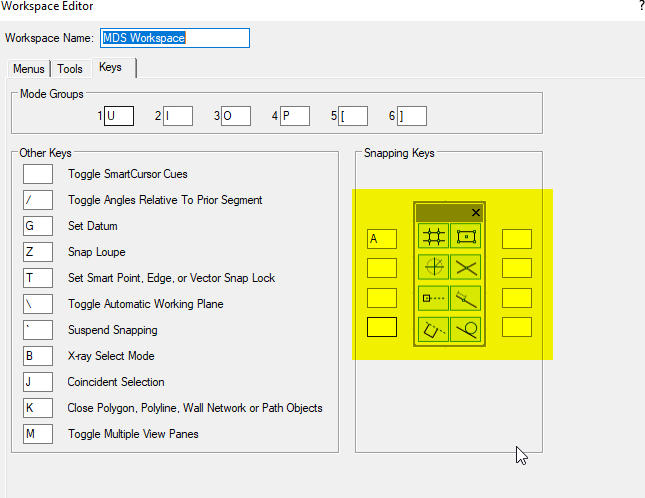
What are your short cut keys for snapping set to in your workspace? I suspect you might be toggling the snap off somehow on your keyboard. I only have a quick key for turning off and on the grid snaps.

-
You can use the move by points tool:
-
 2
2
-
-
Bumping this. It seems such a simple thing. Any ideas?
-
I suspect there is some detailed 3D geometry slowing the VP updates. I had the same thing happening and then discovered it was some curvey custom door handles with I had inserted. I turned their class to invisible in the vp and the renders speed was back to normal.
-
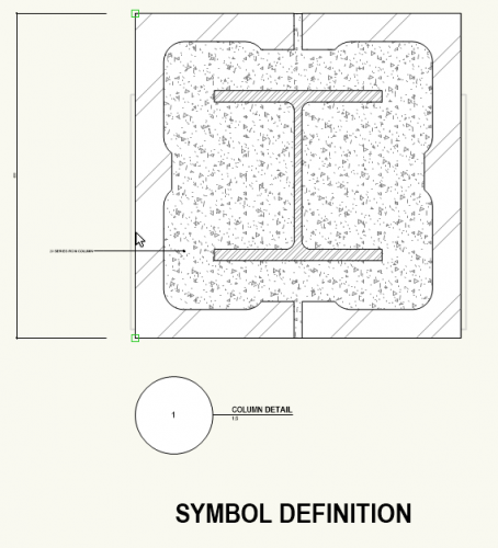
Using page based symbols for construction details is a bit problematic as the detail would typically have real world objects in them which, when inserted would scale up or down to suit the VP/DL scale you are working in. You would then have to re-scale the page based symbol back to a real world dimension.
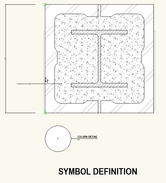
This has got m thinking though and a possible workaround using page based symbols could be:- Create the detail at 1:1 scale i.e. on a 1:1 design layer with all the text objects, (including callouts, dimensions etc) the font size you want on your final drawings. My standard font size is 14pt so I would make all my text objects 14pt. (The text may look out of scale in the symbol but stick with me here...)
- Create the symbol as a page based symbol with 'convert to group' selected.
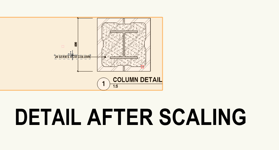
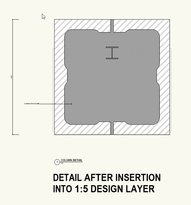
- After inserting the symbol go modify>scale objects> and scale to the required real world size. Be sure to have the 'scale text' option unchecked. If it is inserted into a 1:5 design layer then it will need to be scaled down to 1/5th the size as per example screen shots below.
-
The detail should now be at the correct real world size and your text at your standard font size.
Note that text width may need adjusting and also real world plug-in objects, like the wide flange steel column in the example below, would still insert at it's actual size despite being in a page based symbol.
I'd be interested in any thoughts on this option as I'm just about to start looking at creating detail symbols for our office library.
Example screen shots:

-
1
-
It may be something to do with page based or world based symbols?
-
I had a quick look and it seemed to be working fine for me. I noticed the none class was greyed but it stayed on visible when I changed it. Tried restart?
-
2 hours ago, Matt Panzer said:
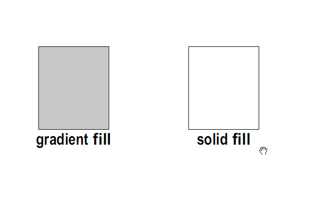
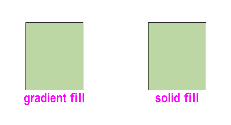
Probably a "Black and White with Grayscale Fills" would be what most users might want?
I don't use B&W files anymore but when I did I often used single colour gradient fills instead of solid fills as the gradients would print in grayscale in B&W.
-
5 hours ago, halfcouple said:
Is it correct that the Replace... button of the OIP does only select objects from open files, vectorworks libraries or favorite files ?
Yes, I've noticed this too. It seems to be the case for me on both VW2018 & 2019.
-
Line weight and EAlexander will have there good reasons for using 1:1 design layers however I think the supposed 'best' practice is to set your design layer scale to the scale you will use for your main drawings. E.g. If most of your plans are at 1:100 then set your design layer scale to 1:100.
That way line weights, line styles, arrow heads, page based symbols etc will scale the same in your design layer as they are seen in your viewports. Text will also read the same size, so 14pt text on a 1:50 design layer will look the same size as 14 pt text in a 1:50 sheet layer viewport.
I remember my days using autocad where I had to increase the font size of text in the model space to match that on the drawing. Design layer scale in VW does this for you.
If you are doing 2d work then you might have a design layer set to 1:25 for sections and elevations and design layers at 1:5 or 1:2 for detail drawings.
-
Yes I think it depends how complicated your projects are. Using file referencing on a small one off project seems overly complicated to me.
If the template is for small projects then it is more straight forward to avoid referencing. You may need to get a system for managing multiple classes, otherwise it can be a bit confusing. My tips are:
Have a standardised class system for your templates.
Set up your template viewports with the preferred class visibility and override settings.
If you are importing third party files then a great little tip is to add a "z-" prefix to their classes. They will then drop to the bottom of your class list out of the way. (There is a script that does this.)
Note that classes are primarily used for setting visibilities of different types of objects as well as standardising their attributes (line type, weight etc).
Generally, for objects placed on sheet layers you want them to be seen, so setting class visibities isn't important. Most of my sheet layer objects are on the none class.
-
Haven't tried it but what about stacked section viewports?
One just for the DTM and the other for your bldg model. With two viewports you could set the attributes of each differently in the "Advanced Properties".
-
With auto-classing now off any new plug-in objects you put in in your drawings will just go on to the active class so be carefull there.
I was thinking the other way you could do it would be to turn the gable window into a symbol and insert the symbolled window into the wall in your invisible class..
-
If you have autoclassing enabled then window objects will stay on their auto-classed class.
File>Document Settings>Standard Naming and uncheck "Enable Auto-classing".
I may be wrong on this as I don't use auto-classing or even window objects...
-
I think you need to simply put the window object in the invisible class. Not change the window classes in the window settings.
If the window "container" object is in an invisible class all of the objects in the window will be invisible even if they are in different classes.
-
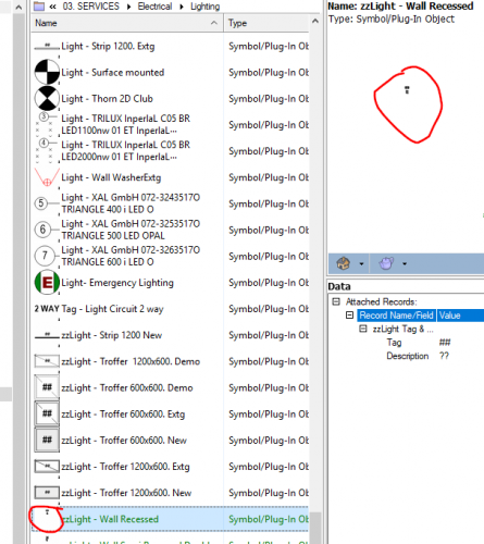
Title says it all. I noticed world based symbols preview well in the RM but page based ones are so small they are useless. Any suggestions?
-
Here's a few things we have incorporated into our templates. I'd be interested to know what other people do.
- Default Design & Sheet layers to the preferred page set up
- Sheet layers complete with title blocks, scale bars, north points etc and commonly used viewports with class/layer & override settings
- Default commonly used classes.
- Default settings set up for all commonly used tools.
- Units & document adjusted to preferred settings.
- Often used scripts.
-
Snap settings set up to preferred defaults.
- We don't generally include symbols as these can be quickly imported from our symbol library.
We started off with just a single general template and kept tweaking it to get it how we want before creating more project specific templates.
-
1
-
Hi Scott.
Perhaps post the file so we can have a look at it?
-
I also tend to have just one file open at a time. This is mainly because I am usually working on one main project at a time. Unfortunately also with VW crashing at random times it means less hassle retrieving drawings.
-
Choose the way the suits how you work. I like using groups a lot and so having only the active class only visible doesn't work for me as usually the group container object is on a different class than the objects inside. If I make the contained objects the "Active only" class they will still become invisible as the container object class will be turned off therefore rendering all objects inside it invisible.
Using layers to keep objects to the foreground is a good method which I use too however sometimes you already have enough layers in a document...
-
1
-


Overlapping rectangles and line type display
in General Discussion
Posted
Me neither. I convert to polygon and hide the edges with reshape tool.