


HEengineering
-
Posts
478 -
Joined
-
Last visited
Content Type
Profiles
Forums
Events
Articles
Marionette
Store
Posts posted by HEengineering
-
-
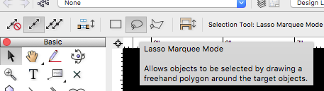
Its a mode within your selection tool. Upper left hand corner when the tool is selected. Many other tools have modes or attributes you can select such as the Select Similar tool.
-
3 hours ago, Andy Broomell said:
Yes please! This is one of those strange things to explain to new users.
I tend to encourage students to always use Renderworks Style resources, as I've found it almost always leads to better results in less time.
I think more info on what you refer to as Renderworks Style would be helpful. Ive typically used open GL for most everything rarely touching any other settings. Mainly because It can get pretty confusing. I get lost between the custom Renderwork styles, custom Renderwork options. I will say we do very little rendering and open GL works for all, but still leaves me wondering if there are not better options. I feel as tho maybe I could get a style saved, and apply to all renderings.
-
Understood. Well hopefully we have a few more years with 14 15 versions.
-
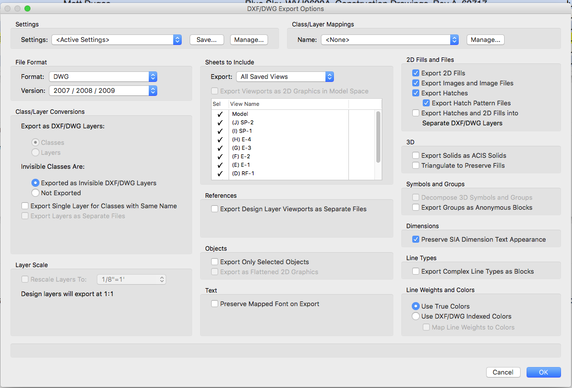
we have discussed this in the past Matt. I have tried the DWG export as well. The issue is it spits out separate files for each saved view. The old way was nice as it was all one file. Maybe there is a way to do it and I'm simply not aware?
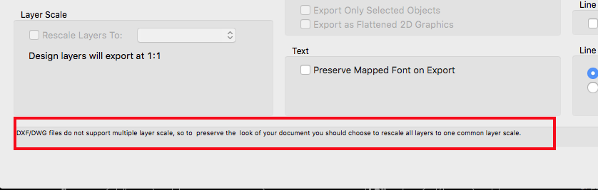
The other issue is the different design layers seem to export out only 1 scale. Might have to share a few files to show what I mean. Seems any saved views that have multiple design layers with different scales are all set 1:1 upon export. The export dialog seems to confirm that. Seems we may be painted into a corner here?
-
One thing I forgot to ask, as a few of the guys here asked as well, is there any hope for a Panzer CAD viewport pack for the 16/17 versions? We are really just after the Saved views>to viewports option.
Our teams love the fact VW can be done with saved views and there is no need for VP's, In fact that is why we moved to VW from Auto Cad. It also makes it easier for new trainees. I've seen much of the debate on this workflow, but none the less it is the best for what we do here. I have tried the sheet view approach, and it just doesn't pay off in our industry, nothing is done in 3D in telcom.
As of now that's the only way I know how to convert a saved view workflow, and still provide the customer with a DWG file in the end(which comes up periodically, most are content with a pdf).
If there is another way to do it Id love to know. I have asked the forum a few times to no avail.

-
Seems it was maybe user error. The second attempt worked as expected. I appreciate the time. I think you have given me enough guidance to work thru it tho.
-
II jumped back into a view to adjust the page size and the viewport size. Everything went smooth, except after resizing and ungrouping the view port it appears to not recognize the camera match object. I will try again, just wondering if this is normal behavior. Either way if I started from scratch it would resolve it. Was just attempting to see if it could be adjusted vs starting over.
-
Sure can Matt. Like I said the final presentation is 300 MB. It will be a couple files since like I said it was several views. Ill describe each in a PM.
-
@Matt Panzer any thoughts here??
-
What kind of file sizes are people coming up with when exporting a VP to a batch PDF? 300mb seems large to me? Ive tried various methods of sizing down the DPI in the batch print and the VP on the sheet layer in each file. When I copy the viewport over to the Mac Preview program the images are in the 50-90mb range? Does that seem right for an open GL render??
-
I have 3 files with 3 separate views. Ive model in my file and then exported to PDF. The issue is all 3 PDF exports combined are over 300MB. I need to get this close to 30MB or less. My VP are under 100 dpi and my pdf export is is set to 100dpi.
There has to be a way to make this smaller without going into PS6 no?
-
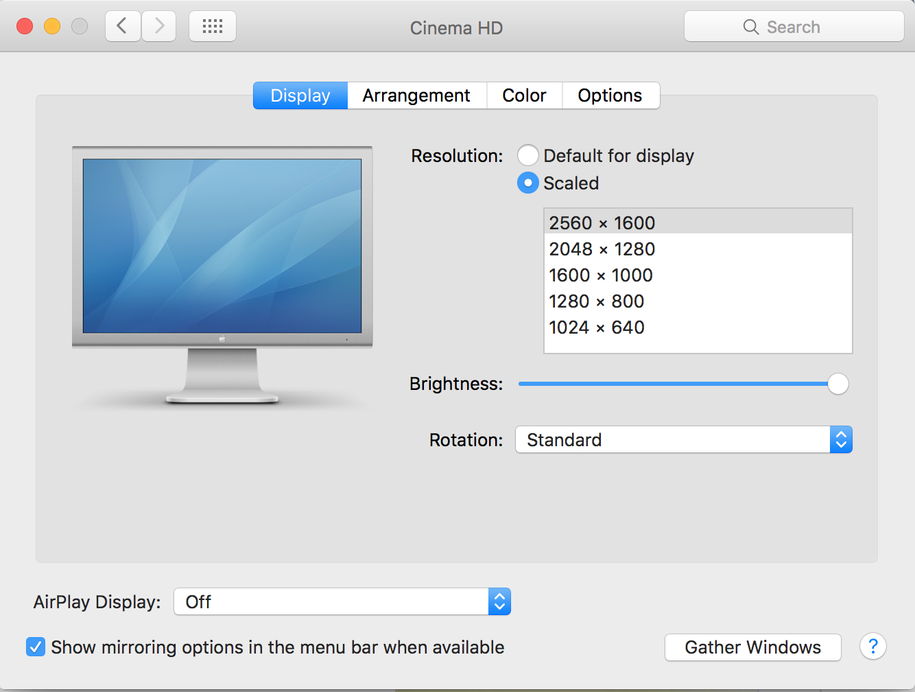
Actually running an old 30 inch Mac cinema display(2560x1600) off a 2014 4k 27" Imac(2560x1440). Im no hardware expert. Seems like I should be ok? I run VW on the 27" Imac almost exclusively.
-
On 7/25/2017 at 11:41 AM, JimW said:
How about a
AMD Radeon R9 M290X 2048 MB?
-
Method 1 seems to currently be the best for our workflow, which is usually 2D details and line work. I find this the simplest method for new users as well.
Our industry is more centered around utility design then Architecture. So while we do occasionally make some viewports and renderings, 90% of what we do has to be 2D not only for the client but the muni too. I find creating subfolders for parts and details even with text works great.
Id love to create and model everything 3D, but its really hard to justify the upfront time, when our expected turnaround time is so short, and every project is so unique, very few similarities carry from one site to the next.
It also would require uprooting our entire office workflow, and while I love to embrace change, this goes a little beyond that for us. I fear we will never change that workflow unless we are forced to. The beautiful thing about 2d is its simple and it works. All these links and viewports start to become a little more than the avg drafter can often handle. When an issue arises it can often times be crippling. You dont' really have that with 2D line work.
The best part about this is you can search the RB and all your favorites for the name of the symbol. So I can search all my files in one swoop rather than pecking around in various "favorites" it becomes a live searchable database! This is the best part hands down.
This all pertains to 2016 Resource browser, while the 17 browser has been reinvented in a sense, we havent made the full move over to 2107 yet.
To add to this I would love to see each method explained and used in a webinar or tutorial. Sometimes you know how to use the tool, but not sure what situations you can apply it in!
-
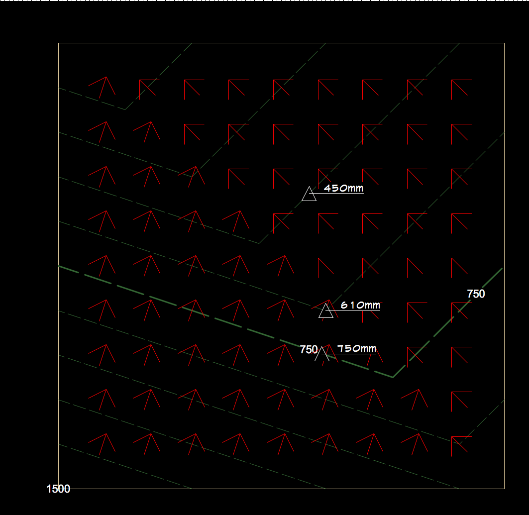
I don't believe what your seeing is 1 of 3 stakes. I think what you are seeing is the major contour callout set in the site model settings. If you look under preferences there is a setting to show 3D loci, which I think you used initially and should show up in a 3d view, however your looking for the stake.
Another option would be to come back in and add the stakes onto the model where you want them. I think the model is generated from the stakes, and often used as a site modifer.
While testing your file I was able to get the stakes to show up in top/plan only, and that was after I added them in myself. Im not sure they will actually show up in 3d views. If you place new stakes in top plan view the will show the label and the elevation at which they were located.
Hope this helps a little.


-
In my experience a snap shot is just that. A snap shot of the model, it loses its connection to the model however. So any updates to the model will not update a snap shot. Often I reserve snap shots for when Im done. They can be layered and edited if you so choose, often I just use the snap shot and copy it over to the working file, so as to keep the model seperate and still editable in another separate file.
-
Its really a nice tool Zoomer, have a look if you are ever in need of a photo sim and looking for something a bit more streamlined than say Photoshop. Our industry requires it a lot in particular municipalities. The best part is you get great resolution from the model, where as the old way of layering photos really doesn't have this clarity, at least in my personal experience.
Copy the VP and past from clipboard Into Preview and your good to go.
-
Awesome Matt. We really like this feature and I think weve got it nailed down at this point. Screenflow videos rock.
-
Im hoping @Matt Panzercan give me a quick yes or no here. I notice that you can set multiple CMRef point on either the same design layer or a new dl. However when switching the CM ref point in the settings it doesnt seem to matter which ref point I associate with the photo, the both move and cannot be independently manipulated from what I can tell??
-
I have used this a few times now and getting better. Wondering if I have to show the same object in 3 different locations on the same image. Im thinking this should be possible, however never trying it Im looking for any pointers or insight?
-
Ill start by saying we work in saved views. At this point we still use the Panzer CAD View pack plugin to convert saved views to sheet views and then export using the sheet views.
My concern is Panzer CAD isnt compatible beyond 2014 and we are in 2017. Our workflow most likely wont change. So my question is can you actually export a saved view file to a dwg in a way that will be useable? We have tested this in the past but seems it wont work, maybe we missed something?
oddly enough this option shows up, but never seems to work for us.
-
@RussU do you actually export a file for the 5 axis or? Ive always wondered if there was a way to export a file for a machinist? Im curious as to what is the workflow for this if you don't mind sharing?
-
Pat your knowledge in this community is so helpful. I always appreciate your level of understanding in this software.
The reason I asked about rendering is I was wondering how I could adjust and change the look of the linework when displayed thru the viewport. I would be looking for something more similar to hidden line rendering, or similar type adjustments.
Am I to assume those adjustments are limited to SLVP? Id like to try and show dashed lines in pipes, structural members, and similar items of that nature. For example a cylinder shows with several faceted corners as seem on the screen shot. I like it to show only 2 dashed hidden lines in the inside.
Also is there a way to keep the dlvp from moving around the screen when switching views?
-
I hi-jacked another thread regarding this so Im going to start a fresh one. We work with saved views here. We put all our detailing on design layers. We then activate those design layers on the saved views and those act as sheets. We have in the past used sheet views as well, but for what we do....2D is where most of our work is at.
With that being said I have now figured out that it appears you can use design layer viewports in this workflow.
I was able to model a pedestal in a design layer that will not be set to any saved view.
Then create DLVP showing different orientations. 2 new design layers(one for each DLVP) and turned those on for the saved view as well as the other 2d details on design layers.
Ive posted a few snap shots to help clarify. Unfortunately I cannot file share this due to policy.
I have 2 questions for the VW power users.
1. Is this actually a normal workflow? Or are these DLVP not meat to be used this way? Also you cant render a DLVP without messing up all the other details that are 2d on screen Plane. See attached.
2. Where is the best place to put ur annotations for something like this as there is no annotation space on a DLVP. Would I be better to dimension on the throw away design layer were the model resides, or on the design layer were I paste/create the DLVP?
The motive here is to try and find a way to make use of DLVP in the very small amount of situations where we have have multiple details changing, and we could simply edit the model(in multiple views & orientations), and have the DLVP update all the other details. Hopefully the screen capture helps clarify.


Copying a selected area of a line drawing
in General Discussion
Posted
Something is getting lost in translation, as I would agree with Benson. If you create a viewport of the desired area you can adjust the crop and then convert the viewport to line work, which is not attached to the model anymore?