

.jpg.3776b4299d3cc626db6bdb79aec2aa12.jpg)

Gabriel Chan
-
Posts
114 -
Joined
-
Last visited
Content Type
Profiles
Forums
Events
Articles
Marionette
Store
Posts posted by Gabriel Chan
-
-
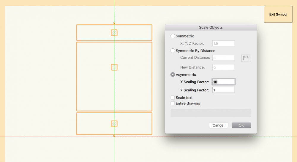
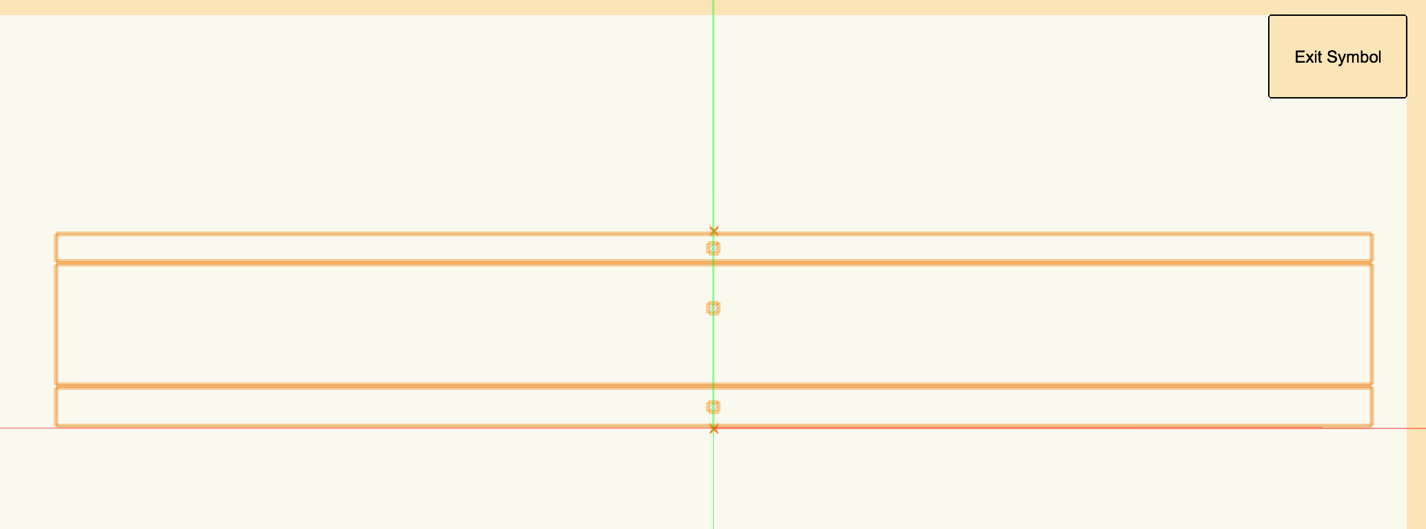
Hi Ross,
I haven't been able to replicate your problem. I copied your master symbol and then pasted in a new file. Attached snapshot of before and after asymmetrical scaling. The sub symbol still remains as is though. In fact, it remains as it was, which I do believe is the right behaviour.
Could you share how you scaled the master symbol?
Gabriel

-
Hi Ross,
As far as I'm aware, while editing the master symbol, any scaling done in the edit master symbol window should not scale sub symbols.
Do you have a sample file to demonstrate what you aren't able to achieve?
Gabriel
-
What I understand is that the plugin is something created by MA, not Vectorworks, so perhaps this is the wrong platform? Also, there is the advent of GTDF or General Type Data Format, which is still a few years before it matures into something useful, but hopefully then this VWX-->MA plugin will be a thing of the past.
Gabriel
-
Maybe this link might point you in the right direction.
-
Hi all,
Interesting observation here... I was setting up my layers with layer elevation not = 0.
For example, some of my lighting towers rest on the plane which I shall call ground zero. Some towers are below this plane by virtue of the nature of the outdoor space so I have an elevation of -1000mm.
So when I hang lights on towers which were placed on layer elevation with a negative value - let's say the tower is 15m tall placed on a -1m layer elevation which gives us a net height of +14m, the lights oddly point upwards instead of their usual downwards position.
I have fiddled with the default settings for the orientation of lighting fixtures so I can safely eliminate that as a possibility. On the same file, lighting fixtures that were placed on layers with elevation of 0 and above pointed down as normal.
A case of a bug there or is this intended? And if intended what could the possible applications be?
Gabriel
-
On 04/04/2018 at 3:04 AM, Mickey said:
Considering how stupid my work flow is with VW2018, project sharing, LW, and MA export adding this extra step isn't that big of deal.
LW is not compatible with project sharing to begin with. Explicitly stated on LW website. I've had to choose between project sharing and LW sync for a relatively large show - around 800 fixtures. Decided to give up project sharing over LW sync. Too painful to not automate paperwork at that fixture count.
Gabriel
-
Vectorworks 2017 latest service pack isn't without its flaws if I'm to be honest.
I have only managed to run the MA export plugin when selecting the export to single layer option. And that means a lot of cutting and pasting of fixtures to different layers on the MA for a clearer break down of the rig.
Exporting by position does not seem to work. Has anyone managed this and maybe would like to share?
Gabriel
-
So I hear that the GDTF is coming along... a dream come true or an April's Fools joke?
And if this update is coming along... which version of VWX will it be for?
Gabriel
-
10 hours ago, Steve Clarkson said:
What about Multicircuit?
I did read that in a Multicircuit instrument the end elements must be different than the interior ones... not sure exactly what that means
I'm pretty sure end units don't need to be different. For groundrows at least.
The end units only want to be different because of the 3D representation of the yoke for multi batten hung fixtures. You would have the middle units have just the horizontal section of the yoke while those at the end have the "L" section come down to the side of those units. I tend to also insert clamps on the units so I end up with, for example, a 4 batten cyclorama flood that hangs horizontally on two clamps, not unlike in real life.
Gabriel
-
@scottmooreyou've got my vote here!
Definitely for more drag/drop control over shutters and interactive zoom. With sliders to control beam and field angles already in place for Light objects, having to apply that to Lighting Devices shouldn't be too far a stretch?
Gabriel
-
On 17/02/2018 at 6:44 AM, MiniToVW said:
when I run one of them, the other one will log out automatically?
That is exactly what will happen. Remember to save on your first machine before you start up the second.
Gabriel
-
 1
1
-
-
I tend to just reissue the entire lighting package with all the revisions included. Used to send out individual sheets that required revisions but found out its more confusing for the technicians as they then need to sift through the corresponding outdated sheets to replace them with the updated ones. A full package revision issue is more wasteful in terms of print resources but it guarantees the most updated documents get to the technicians and minimizes errors during the hang.
Just my my two cents worth.
Gabriel
-
Happy to know you solved your problem. Apologies for being late to the party, something caught up at work!
-
If you don't mind maybe send me a file with just the symbol?
Or if this is from a stock inventory shipped with Spotlight just let me know which symbol it is.
Gabriel
-
Hi Sheriff,
Is there any class nesting in your symbols? It may be a case of the symbol being built from different classes - are those classes on as well?
Gabriel
-
On 24/01/2018 at 1:08 AM, Mickey said:
I've had success with 3.3.4.1. It usually takes me several passes of export/import before the data looks correct in the console.
Sometimes I'll do it in waves. It's always the conventional fixtures that get me trouble because I twofer them, and have multiple instances of the same channel that confuses the export.
What I do in that case is create yet another file, and delete all of the moving lights, and a 3rd file with all the movers, and no conventionals.
The movers get exported by type, and the conventionals in a single layer.
It all takes some hoop jumping but way faster, and more accurate than having to patch a large show directly in the board.
Thanks Mickey, will keep that in mind on my next show.
Cheers!
Gabriel
-
Interestingly, I also had this problem but I'm still in VWX 2017. Tried the export by layers and export by instrument options - neither worked.
The export all in a single layer option was the only one that worked. I ended up going that route and doing the cut/paste layer on MA.
I suspect it's possibly the MA version 3.3.4.1 issue more than Vectorworks as I had no trouble with the plugin export on VWX2017 and MA3.2.2.16.
Gabriel
-
On 11/01/2018 at 9:32 PM, markdd said:
This idea might be a good workaround to get you near to what you are looking for:
You could make special "Instrument Summary" Symbols. The 3D views could be created in a worksheet and then placed as a screenshot into a duplicate of the instrument you want to count in the Instrument Summary Tool. For the Instrument Summary tool to count the summary symbol the Light Info Record Instrument Type needs to be identical to the symbol you are substituting.
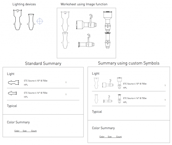
I have done it with a horizontal orientation, but you could arrange the "Summary"symbol any way you like. Take a look at the file which I have attached below.
Hope that helps.
Mark
Hi Mark,
Finally got down to replying - been a busy week with three plots to finish up! By screen shot did you mean literally a preview snapshot? I think I have gotten most of the steps right except for the screen shot bit - similar logic to creating multiple circuited symbols in that sense.
How do you create the symbol out from the worksheet screen shot though? Doesn't that inherently convert the symbol into a jpeg/png? I was wondering if I could say flatten the 3D object lines in hidden line render in front or side view and convert that into the symbol?
Gabriel
-
I'm not sure if the suggestion for layer elevation helps in contour mapping - was just offering a suggestion.
What I do use them for however is when I need to draft out towers with lighting fixtures (I'm from the spotlight / previz community) where the fixtures share several XY positions but have different Z values as they stack one on top another.
As we do quite a bit of data assignment on these fixtures - i.e. Channel / unit number / Addressing and so on, I have found that being able to isolate every tier of lights while working in the Top/Plan view helps with my work flow. At the same time it organizes my fixtures in the correct 3D space.
Just my two cents worth.
Gabriel
-
On 15/10/2017 at 5:03 AM, Art V said:
Autocad and it's dwg based competitors have a command called "elevation" that allows you to set a height. Anything drawn in top/plan view will be at that elevation, which is useful for e.g. drawing a contour line.
It might be nice if VW would have a similar option to set an elevation for top/plan at which all planar objects (e.g. a contour line) will be drawn. That could avoid repeatedly adjusting z-height or other workarounds.
This elevation should be relative to the layer's z-height, or optionally independent of that or take the layer's own z-height into account and adjust the z-height after confirmation if you want that.
Briefly reading through this thread - For elevation, if it doesn't drastically affect your workflow, maybe you could try putting them on different drawing layers? It is possible to set each layer to their own elevation in the pop up dialog box.
Gabriel
-
@markdd Are you on Vectorworks 2018?
Tried opening the file over dinner break and the file is "an unrecognized file" on my machine.
I'm currently on VWX 2017 macOS Sierra.
Gabriel
-
On 11/01/2018 at 6:40 AM, Lightwright said:
Lightwright's focus coordinates are text fields and in practical use rarely contain coordinates expressed as X/Y values. In most cases, the entry is something like "6L @ 4", which means 6' SL of center and 4' upstage of center. Other times, they can be something like "Standing on Sofa" or "Leaning on SL proscenium".
So while focus coordinates could possibly be brought from Vectorworks on a one-time basis into Lightwright in a future release, they would never be able to transfer from Lightwright back to Vectorworks.
Thanks for clarifying. I do tend to insert the LW equivalent of XY coordinates in the same field as mentioned - i.e. "6L @ 4" while descriptions such as "Standing on sofa" tends to be in the "Notes" field.
I could however see the possibility in spreadsheets to append a suffix "L" or "R" based on the positive or negative values of the x-coordinate in VWX and perhaps assign it to a user field? Maybe we aren't that far off from a text string based field in VWX that might then suit LW export field? Purely conjecture of course. And absolutely out of my league!
One can always wish! 😅
-
12 hours ago, markdd said:
This idea might be a good workaround to get you near to what you are looking for:
You could make special "Instrument Summary" Symbols. The 3D views could be created in a worksheet and then placed as a screenshot into a duplicate of the instrument you want to count in the Instrument Summary Tool. For the Instrument Summary tool to count the summary symbol the Light Info Record Instrument Type needs to be identical to the symbol you are substituting.
I have done it with a horizontal orientation, but you could arrange the "Summary"symbol any way you like. Take a look at the file which I have attached below.
Hope that helps.
Mark
Thanks Mark! Will have a look into it after opening a show this weekend. The workaround solution looks promising!
Gabriel
-
On 13/10/2017 at 4:34 AM, Wesley Burrows said:
I am curious if the below were generated with the instrument summary tool or if they are a custom worksheet, or just manual text with the mode info/QTY: ##. I'm assuming some variant of the later as I can't figure out how to make the tool format with line breaks in this way. I'm also curious about the horizontal one with multiple views of fixtures.
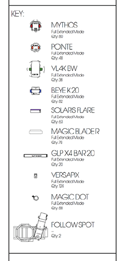
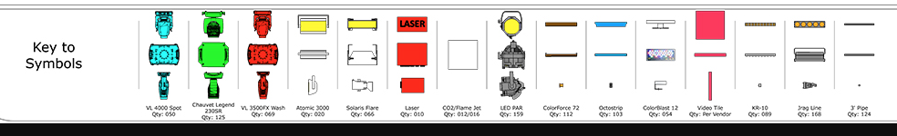
The horizontal one with multiple views seem like a manual creation indeed. Incidentally, I'm also interested if spotlight could in fact create a key that allows us to choose different views of the lighting fixtures.
Lighting rigs these days can be vertically quite complex and I find myself resorting to front or side elevations to best display the intent of the hang.
And with 3D labels already implemented into VWX symbols, it seems like a natural progression to also allow us to display lighting symbols in their front views in symbol keys?
I've been spending some time in worksheets and it seems possible. There is an option to insert images of symbols in their various orientations and I think even in different render states. The hidden line render seems to work best for my work.
Unfortunately I haven't spent enough time to work out the formatting to my liking. Not have I found a way to automate it to the ease of a PIO such as instrument summary.
Perhaps someone could shed light on worksheets that might be tailored for such purposes?
Gabriel


Controlling the behaviour of nested 2D symbols
in General Discussion
Posted
Hi Ross,
Understand what you are trying to achieve now. I'm not actually sure if that is possible though - never had applications where I needed multiple instances of a same symbol.
I think we might have to leave it to the experts. @Jim Wilson?
Gabriel