


DomC
-
Posts
605 -
Joined
-
Last visited
Content Type
Profiles
Forums
Events
Articles
Marionette
Store
Posts posted by DomC
-
-
- Popular Post
- Popular Post
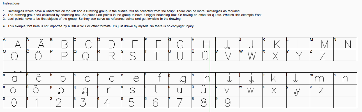
A Marionette PlugIn, that collects a custom drawing (font character, picture whatever) and refer it to a regular font character.
This "Font" is placed into the control geometry container. Also we could just use a blue symbol.
The Heart of the script is a custom node "create font dict" which manage collecting the control geometry. Also it returns a dictionary sequence data type. A dictionary is very useful if you want to have pairs of data. In this case a character and a drawing group with informations forms a pair.
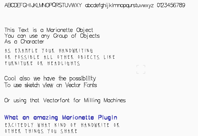
Sure, the script could be improved by several things (multi-line, alignment, page based etc. ) But I think it is very useful to have that plug in. Have fun with it. Maybe you can share your own fonts and your wonderful handwriting here. Thanks.
Usecases:
1. Handwriting Font
2. Vectorfont (ability to use sketch view)
3. For Milling Machines
4. Fast inserting of object sequences
5. ...
Update v2019
1. Script Crashed if input Geometry was None (Integrated a script blocker and an Alert Dialog )
2. Input Dict was always None, because use of an outdated Script command (vs.GetType() instead vs.GetTypeN()). Issue in many other scripts. One of the very rare incompatibilites of Script commands the past Years.
Second Example (Shelve) attached. To take care. This scripts somehow forgives no errors in the object input. So be careful by edit the control geometry. None Input in the Textfield or in the Input Geometry (Symbol, Control Geometry) will Result in crash.
-
 4
4
-
 1
1
-
Quote
2Dsymbol, extrude the 2dpoly by 3m and exit and the symbol becomes a 3D and still holds the records
1. Linking Symbol with Record
- Enter Symbol, DSelect all, Link to Record
- All New Placed Symbols in the Drawing have now a Record Link.
- All existing Objects in the Drawing keep their Recors Link or their non-record Link.
2. Why record Links still there after Extrusion
- If you link the Symbol Container (like above) the symbol is linked to the record, not the poly
- So the symbol always keep the record. Whatever is inside the symbol
b.t.w. think we are rotating in a circle.
I think this is no sorcery but it think we need more specifications. Because all the technique for this is already there.
- Contains the List a unique Room Number (Every layer different or is the Layer Name part of the unique Room ID)?(OK, the Room Number is a Text field in the Drawing. But is this text is already there or is this text in a list at the beginning.
- Is every project on a single story/layer?
- Contains the List an Extrusion Value for the Room?
The other known specifications:
- We need a Name in the Object Info "Name"-Field
- This Name depending on text in a specific class (so maybe an input field for class name)
(Running a Marionette by activating things is not working -> So the better way for this workflow is a python Vectorscript)
- This "Name" value does something after the export to unity model?
Next Steps:
1. I think it is the first step to link objects to room number and room extrusion (bevor we think about symbol extrusion etc.)))
Just a small test with the polys
2. Next find out, how to extrude an object by the extrusion value and how to name the object in the info palette (which seems to be necessary)
3. Find a Way to update and adapt in an easy way, to a new project.
-
Why we need symbols here? Is in necessary to export symbols? Or were they imported from another software?
-
OK
I read the full text :-)
1. Find A way to attach your existing text-fields to a record or room record. Because you will need much time and will make errors by manually enter the room numbers. Attached a Script which will make this.
- First extrude all polys and Ungroup. Do not use rectangles. It will just work with polygons and polylines. Also do not move the extrudes the script access to the content of the extrude and those coordinates.
- Attach Record Format
- Run script
This Script also works for other text-field and infos. With this Script you could also get the class and write it into a record field. Build this more to have a Script which nurse all needed Informations and attach them to your extrude. So could ground all further scripts on this record data. Just an Idea.
3. Script which access the list (see above)
4. Next Step. Whith 3D Info, you can get the zValue of your extrude and Set 3D Info you can reset the extrude zValue.
Maybe a first step for automate the complete workflow.
-
Hi
While nobody has time to build this script for you, maybe I can help you to build it yourself.
1. You Need the Sheet as a Text Tab oder a character separated Text File. You can save that out of excel.
2. Or you copy paste the list into a Vectorworks Worksheet
3. First you have to grab this List. The Script-Part for doing that is available.
Example:
https://forum.vectorworks.net/index.php?/topic/42135-node-example-for-filling-an-area-with-symbols/
And a new and more flexible node to import csv files here:
https://forum.vectorworks.net/index.php?/topic/47801-the-rest-of-domc-nodes/
With this nodes, you will be able to pull your (excel)- List into Vectorworks
4. Next you need a key value. A value, that is part of your excel ist and a value, that is attached to your object in Vectorworks. You have several method to do this:
a. Attach a Record to your room-polygon and manually attach the room number (You could automate room numbering, but this will not match to your list I think)
b. Or you convert automatically your polygons into space objects. Which has automatically a set of recordfields attached.
5. You have loop through your list and through your object (spaces or polys) and let the script search for a matching key. And if the key in list and from the object is identically, you change (duplicate your poly on a new layer and extrude by the value) or directly change the zheight of your space.
Also this script engine is already existing here:
https://forum.vectorworks.net/index.php?/topic/42135-node-example-for-filling-an-area-with-symbols/
6. Also you would be able to use your originally symbols for doing this. I think you have to locate the symbol position. Then go inside symbol and take the geometry object inside of it and move it to the symbol position outside on a new layer as Example. Or you directly change your symbol if it is unique. Maybe this Script can help you to find a way get something from inside a pio (path Space etc.) and place it at the same coordinates like the object was:
This would be a complicate part, because there are no standard nodes which can pull a geometry out of a symbol and place it an the new matching place. But the code inside the node "Obj on Space" shows how it can written in python.
https://forum.vectorworks.net/index.php?/topic/47218-batch-export-of-pdf-thumbnails/
Or the Node "Get PlugIn Position" can help you to move the poly out of symbol. The node is posted here:
https://forum.vectorworks.net/index.php?/topic/47801-the-rest-of-domc-nodes/
Or maybe a much more simple idea:
1. Duplicate your symbols
2. Use the "Convert to Group" node to get the poly inside the symbol
3. After that, you have to attach the symbol name on that poly (or another key see above ... because the poly will forget in which symbol it was) to match it with your excel list.
Convert to Group Node can be found here:
https://forum.vectorworks.net/index.php?/topic/47801-the-rest-of-domc-nodes/
I hope this help to get a start-assist for creating your script.
-
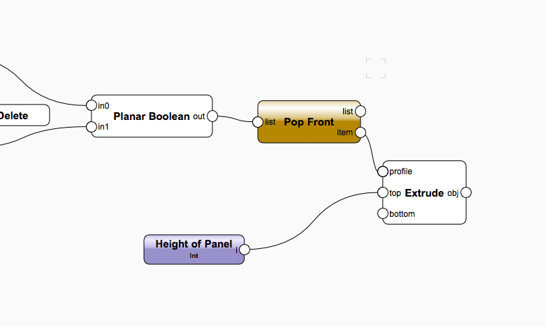
Hi Alan
I also saw that in other PIO Scripts. The Planar Boolean returns the "tool"- object to the Extrude Node. vs.Marionette_DisposeObj(tool) deletes that object at the very end of procedure. And then it's too late, because it was "eated" by the extrude node?
Could be "hacked somehow like this":
                elif self.Params.op.value == 1:
                    newObj = vs.ClipSurfaceN(blank, tool) # blank and tool won't be deleted after this operation
                    if newObj != vs.Handle(0) and newObj != None and newObj != tool:
                        blank = newObj
                        vs.DelObject(tool)
Or with a Marionette Node:
-
Screenthot Attached.
-
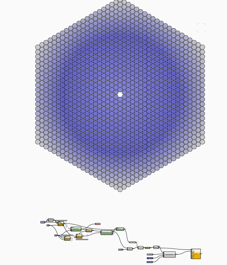
Hm. Drawing the stacked circles is just a grid :-) No hexagon needed.
OK, if order from a center and the colour pattern is part of the idea, there can be a reason to create circles in a specific algorithm.
-
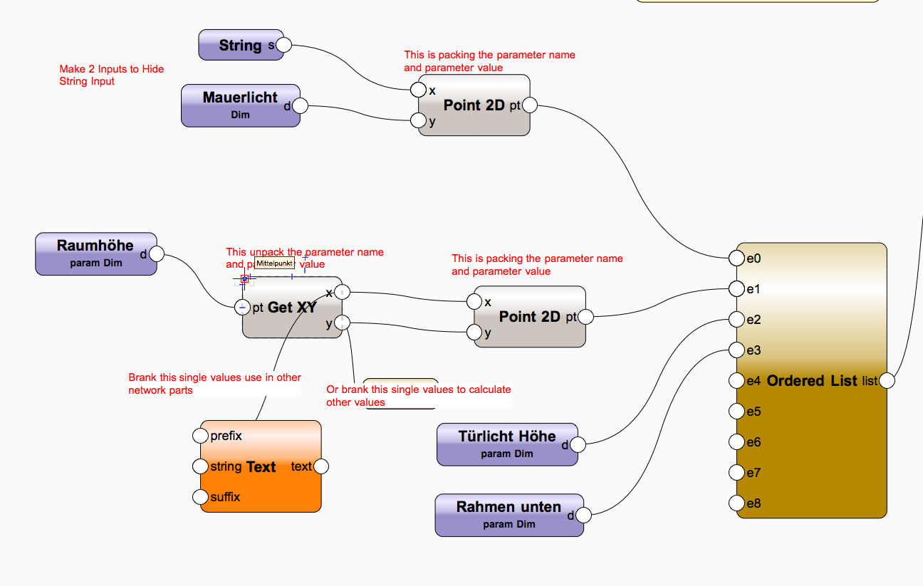
This Project is one of my first one. The scalability of this network is not so good. So every new Feature, has to made inside the reshape node.
1. Because the parameter and the dim is collected in the same input node, this is not directly possible. But you can splitt the parameter name and the dim node in two. Just "Unname" the parameter name input node and it will hide. Screenshot attached.
2. The Parameter Inputs returns a List of ('parameterName', DimensionValue)
If you want to input those input Values in other Network (calculations, Text, Record Fields etc.) you have to split those two values. The (GetXY)-Node can do that job (From the Point Node Folder) So you can use this to feed a text node. If you splitt the input in parameter name (string input) and value (dim input) anyway, this will not be necessary.
Screenshot
-
Always a relevation, an input from the master :-)) Me rookie scripter got so many inputs from Pat and other adepts, thanks at this at this point.
-
Looks like your object are 2D. So maybe this could be an option?
Complex at first view but you can generate hundreds of different Window-Sizes out of one prototype geometry.
-
1
-
-
Hi Matt
Thanks for interesting in this theme. I think you need another (more simple :-) script to make that regular circle stacking.
Idea to solve that
1. We can think in hexagons to draw the circles
2. Create all radius of your point and sort them. from small to big
3. So you have your parameter n-circles (if ever needed)
4. Or checking distance from every circle to the center to have a radial- and not a hexagonal border
5. attach numbers and data to them
6. Labeling them
I try to give you a start ... The rest is routine peace of work :-)
Edit: New Version (Repeat instead of mix2 node)
-
1
-
-
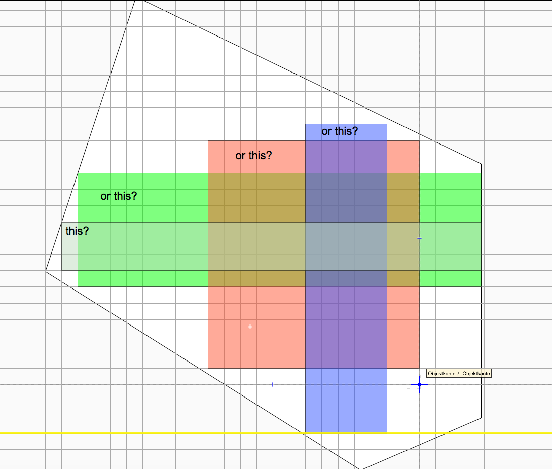
Can an Vectorscript solve this problem? The answer is yes.
If you ask for a Vectorscript function for that: The answer is no.
And the task is not really clear. You want to find the widest rectangle with the height x? Or you want the have the rectangle with the largest area? Or the widest Rectangle which height is minimum 20% (or some kind like this) of the width?
I think the simplest way would be, to make a grid over your polygon. Then you have rows and columns. With that, you could generate the biggest, the widest and the highest recangle.
Not sure, but I think this could be a possible approach. I would do that with python script. There seems to be solutions available on the net. As example here:
https://gist.github.com/zed/776423
This code for that looks quite simple. Maybe that script has to be adjusted. As example store the start endpoint of the rectangle inside the script. At the moment this just returns max area, width and height not the position.
Interesting and useful task ...
-
This looks as a part of the Marionette method to automatically install a used python module.
-
Hi
Im am not sure, what you are planing exactly. To be clear: I have no Idea, but I would like to help you. As far as I can see:
1. You loop all selected Objects in the Layer-Name 'Layer' and apply the function rename().
2. The function rename shows a dialog Box with the handle value (which is a good test to show, if your script works -as far as we don't select hundreds of objects to test)
If you want to use data of those objects you can pull them in your function. like a.E. 'vs.GetName(h)' to get the Name of the object. Or other vs-methods which gets other kind of data.
Then the next step would be, to handle the "other objects in the same layer." to populate them with this data. Maybe with the criteria "((L='Layer') & (SEL=FALSE))" to get all other objects in the same layer?
If you want to delete objects or change stacking order (or other things, that affects the criterial or the order) you should write your handles in a list variable and change them in a second loop (for item in ..... as Example)
-
Hi
I agree, I also wish we had some kind of report Window or Message Window. Which can show more than a few characters and which could add the messages. This would be grate.
"Useless" is a hard word :-) vs.Message shows the last Message Window called in a Script. This could make quite sense but makes it useless to report several happenings during runtime of the script (See, how values change etc. -> this also just would work if we slow-down script). I Think you are searching for a "debug" function, which do not exists at the moment for python scripts inside the script editor.
Maybe "vs.AlrtDialog()", could be an alternative to show messages. I use this, if I have only a few values I want to debug.
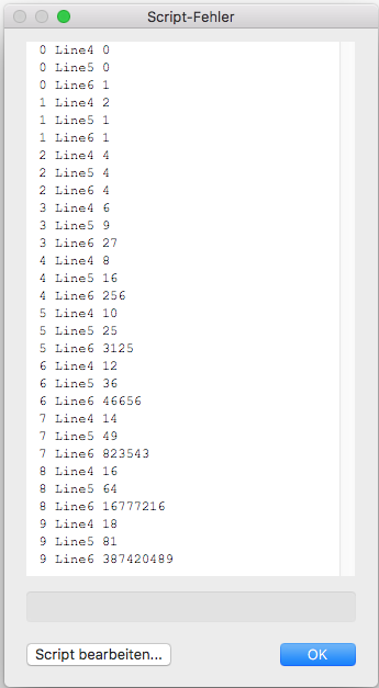
Also we can switch on the Program Option "run script in debug modus" and use the print() command. I often use this, to check values in a loop. Where vs.AlrtDialog() would open endless dialogs.
Example:
for i in range(10):
    print(str(i)+' Line4 '+str(i+i))
    print(str(i)+' Line5 '+str(i*i))
    print(str(i)+' Line6 '+str(i**i))
Besides that ... cool, we have colored python code now in the forum!
This code returns values in an "Error-Window"
-
1
-
-
Accidentally, we all try to solve the same problem at the same time :-) My solution:
SollWinkel = 45

def DoSomething(h):
    if vs.GetType(h) == 15: #Symbol in Drawing
        x,y = vs.GetSymLoc(h)
        #vs.Locus(x,y) #Test Symbol insertion Point
        IstWinkel = vs.GetSymRot(h)
        Winkel = SollWinkel-IstWinkel
        vs.HRotate(h, x,y, Winkel)
    return()

vs.ForEachObject(DoSomething, "SEL=TRUE")
Always most difficult to find the right script commands.
-
@Patrick
Very useful node for different use cases. Dragged in my Node-Library ... Thanks for sharing.
-
This Marionette Object Shows its layer name (last word) and the layer stacking order as a label. I often create documentation inside Vectorworks and do not want to use other applications for that. All we need is Vectorworks!
Contains some custom nodes:
1. "GetAllLayer" A List of Design Layers and a List of Sheet Layers
2. "Backward" A node to send an object in background (did not fount a native node for that ..?)
3. "GetLastWord" split the last word from a string
4. "GetObject" Wrapper to grab a Text Object with a Text Style and to transport this Textstil by copy/paste the script
Nothing spectacular but could be handy and really helps saving time compared to manually texting or stamping a counter on every layer. Also with the "GetLastWord" node, the layer can contain the chapter in his name.
-
Lilith
Happy to see you pulled some launch assistance out of my workshop and are on the way to speed up some workflows :-)
I think your script will work fine. By the way, if you want to exclude all sheet layers (If you create a New Sheet, your script had to be adjusted) in your "object-collecting-function", you can do this as follows:
def DoSomething(h):
	t = vs.GetObjectVariableInt(h,154)
	if t == 1: #Vectorscript Appendix 1-> Design Layer, 2-> Sheet layer
		GefundeneObjekte.append(h)
-
I Think changing dynamically the Node definition is not possible because of different reasons. Anyway we should not hack the internal name without rerun the node definition process properly, because this is stored (cached, compiled, don't know) somewhere unknown when you exit node editor.
this = Marionette.Node('ThisMustNotBeChanged','ThisCantBeChanged')
What could be changed is the node Name in the Info-Palette. Which is stored in a normal record format. Then you could implement the following code in the RunNode method:
def RunNode(self):
    calcType = self.Params.calcType.value
    a = self.Params.a.value
    b = self.Params.b.value
    if calcType == 0:
        vs.SetRField(self.Handle, 'MarionetteNode', 'NodeName', 'Add')
        self.Params.c.value = Marionette.TupleMap(operator.add, a, b)
    elif calcType == 1:
        self.Params.c.value = Marionette.TupleMap(operator.sub, a, b)
        vs.SetRField(self.Handle, 'MarionetteNode', 'NodeName', 'Substract')

    vs.ResetObject(self.Handle)
So after running the node (the script) the name changes. Better than nothing?
-
1
-
-
Very nice, thanks for figuring out that ...
-
@Alan Woodwellthanks for posting them.
Those are outdated versions of the included nodes. Except the "Schlitz"-Node I used for the slot pipe (I hope this is nothing obscene in english :-) example.
Passing through my mind, I never posted that. Movie and example of that "Schlitzrohr".
-
1
-
-
The Descreption was all right for the first version of the Get Bounding Box Node. Because the Script-Command does exactly this and returns wrong results in wrong views.
The Marionette engine I think, newly run the script in a Top Plan view. So the Descreption should be changed.
From a isolated view, the desception is matching exactly for the RunNode() Methode. But the Node runs in the Marionette class, which changes to TopPlanView.
TrackObject procedure
in Python Scripting
Posted
Great Information! That seem to work.