


WhoCanDo
-
Posts
417 -
Joined
-
Last visited
Content Type
Profiles
Forums
Events
Articles
Marionette
Store
Posts posted by WhoCanDo
-
-
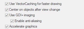
I exported the PDF from my drawing before importing it again.
Rasterize PDF was not ticked so it should have been vectorized.
-
I just updated to SP6
I've lost my drag and drop.
I can't drag vwx, dxf, pdf, dwg, etc. and drop them into my VW2024 SP6
Can you ?
Additionally, when I Import a .pdf and ungroup it, after deleting the bmp and blackout page, there is no vector drawing left.
Note: I am on a Windows 11 PC at the moment.
-
After all this time, I still can't get a reliable search happening.
This code supposes this hierarchy ..
IfcMechanicalFastener
Tekla Bolt
Bolt Name
and it works well.
However, I have a client that sent me an IFC file with this hierarchy ..
IfcMechanicalFastener
IfcMechanicalFastener
Bolt Name
and it doesn't work when I try and find the Bolt Name.
Can someone suggest a reason please ?
Procedure SelectByIFCProperty; {December 13, 2019} {© 2019 Patrick Stanford pat@coviana.com} {Licensed under the GNU Lesser General Public License} {Selects all objects that are defined as IFCMechanicalFastener } {and have an IFCPSet of Tekla Bolt with a non-blank Bolt Name attached.} {Here be dragons. No Warranty Expressed or Implied. Use at your own risk} Var B1:Boolean; S1,S2,S3,S4:String; N1:Integer; Procedure Execute(H1:Handle); Begin B1:=IFC_GetPSetProp(H1,S3,S4,S2,N1); If ((B1=True) & (S2<>'')) then SetSelect(H1); End; Begin S1:='Tekla Bolt.Bolt Name'; S3:=Substring(S1,'.',1); S4:=Substring(S1,'.',2); DSelectAll; ForEachObject(Execute,((IFC_ENTITY='IfcMechanicalFastener'))); End; Run(SelectByIFCProperty); -
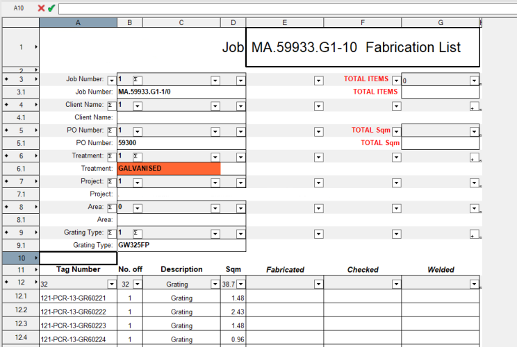
I'm formatting a worksheet for a job.
In the "Total Items" cell, I want the answer =sum(B12, B13, etc.)
However, this doesn't work.
Then I tried summing the answer under the list in cell B17 and tried the formula =B17 in cell G3. That didn't work either, even though the B17 cell showed the answer.
Please scroll down past this worksheet layout.
Then I tried writing a macro. On it's own ( with WSScript_SetResStr (Num2Str (0, n)); replaced with Message (n)), it returns 32, which is the sum of cells B12 to B16. Nice.
However, calling it with =RUNSCRIPT('Total Items') in cell G3, it crashes VW.
If I put =RUNSCRIPT('Total Items') in B17, and =B17 in G3, it makes a mess.
Any ideas or reasons would be appreciated.
procedure Total_Items; var i : integer; n, V : real; h : handle; begin h := GetObject ('Grating - Fabrication List'); for i := 12 to 16 do begin GetWSCellValue (h, i, 2, V); n := n + V; end; WSScript_SetResStr (Num2Str (0, n)); end; run (Total_Items); -
So, finding a work around wasn't that difficult. This is how I solved it for those interested.
The reason for making a Database line was to get the Record Value from an object, with a record attached, and list it on the same row as the Logo.
The row must be of Spreadsheet type, and then the cell value =IMAGE(N='Logo') works.
I wrote this macro and the added this formula to a cell to the right of the Logo =RUNSCRIPT('Name of script')
Many of you will recognize the method.
procedure Fab_List_Value; procedure Get_Value (h : handle); var V : string; begin V := Concat (GetRField (h, 'Value', 'GrWeight'), ' ', GetRField (h, 'Value', 'NtWeight')); WSScript_SetResStr (V); end; begin ForEachObject (Get_Value, ((L = 'Objects') & (C = 'Object1'))); end; run (Fab_List_Value);-
 1
1
-
-
Thanks Pat,
I feared that would be the answer.
Thanks
-
Hi,
When I insert =IMAGE(N='Logo') into a spreadsheet cell, it shows me a picture of a logo. Good.
However, if I make that line a Database, it displays "False", not the picture.
Note: the named item is a 2D symbol.
The following link says I can do it for spreadsheet and database cells, but how ..
-
Interesting Kevin,
After a bit more testing, and you suggestion of "same direction", I think I understand my error.
Because the circle wouldn't Loft, I changed it to a polygon, but because there was no "convert to polyline" tool, I also changed the polyline to polygon to match.
Big mistake.
They wouldn't Loft either, so I changed them both to Nurbs and that's why it lofts to a group and not a Generic Solid.
I will have to remember that the polyline should never be changed to a polygon before changing to a Nurb, but a polyline or polygon can be changed directly to a Nurb.
-
Hi Virtualenvirons,
Even though I have created this part using multiple extrude, your questions are valuable for other components I need to draw.
As per my initial post, the circle is 60mm diameter and the oval is 30mm radius and 77.49mm long. It's actually a slot. The finished height is 90mm and the wall thickness is 5mm.
I would be interested in reading your step-by-step method of creating the same object with Nurbs and Lofting.
-
Yes, but I couldn't "Closed" it. The Close button would not stay ticked even though it was not greyed.
The loft created multiple Nurbs and grouped them. It did not merge them into one solid/surface as I was expecting.
-
Nice one Tom.
That will keep me going for quite a while.
-
Thanks Tom.
Not having done much 3D stuff, you help is wonderful.
However, if I set the Shell tool to 5mm inside, how can I get it to punch through the bottom 5mm ?
Is the only solution to make the object higher and subtract solids to clip of the bottom 5mm ?
-
The loft is 1024 Nurbs and I can't get them to add.
I tried Generic Solid but it rejected the objects.
I tried Adding Objects but it rejected that too.
I'm not sure what you mean by Multiple Extrudes because there would have to be thousands to create a smooth surface.
The Shell is the easy bit LOL
-
I thought this would be easy by creating two objects and subtracting solids, but now I find that the shape made from Nurbs ends up as a group and can't be subtracted.
Therefore, I'm calling for ideas please.
Here's what I am starting with ..
 The oval is at level 0, and the circle is 90mm higher. This circle diameter is 60 and the oval is 77.49 if anyone is interested.
After several attempts, I found that the shapes had to be converted to Nurbs and the with Loft Surface tool, I could make this "solid", so I thought ..

With this and another, which is smaller so I can make a 5mm wall thickness, I wanted to subtract solids to make a tube, but it's not a solid, it's a group of Nurb surfaces.
I obviously went down the wrong track, so any help would be appreciated.
-
Thanks Pat,
I had proposed too after inquiring for a solution, if it was available.
-
Yes. Closing the file and opening it again does fix it. I don't need to close VW.
The error re-occurs only after repeating the duplicate and rotation process again. The first duplicate and rotation remained constant but the second has the error.Files attached.
-
"Do you want this app to make changes to your device."
I get this message each time I start VW2024, by both starting the app directly, and by opening a file which opens the app.
I completely uninstalled VW and reinstalled without luck.
-
This video is with the object at the origin.
The first video was on a PC with Windows 10 and this one is on a laptop with Windows 11. There are no other similarities except they are the same version of VWThe file is attached. Just follow the instructions and see if it happens for you.
-
This has been happening in 2024 and can be quite difficult to work with.
I created a 3D set of panels on the right and then picked the first panel and then duplicated it and rotated it to get the left side view.
However, when you see the attached video, I am zooming in and out, and the top view flashes before returning to the side view.
This is what is happening at the moment, but I also get the opposite. Sometimes I will do the same duplicate and rotate but end up with the top view, and I will only see the side view when I am zooming in and out.
I've tried switching layers and back again, and choosing top plan view, but only closing the file and reopening it solves the problem.
Any ideas ?
-
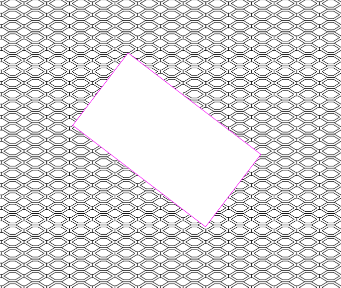
When filling with the pattern, the result is correct.
When filling with a tile, I would expect something similar. The pattern should not cover the cutout.
-
There use to be and AutoCad help sub-section, but it disappeared.
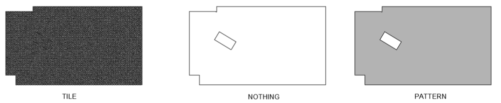
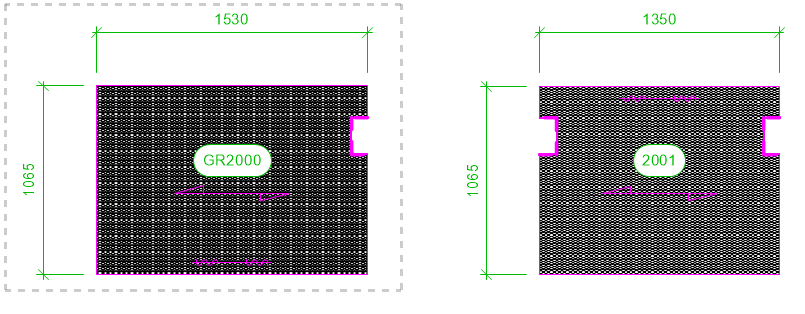
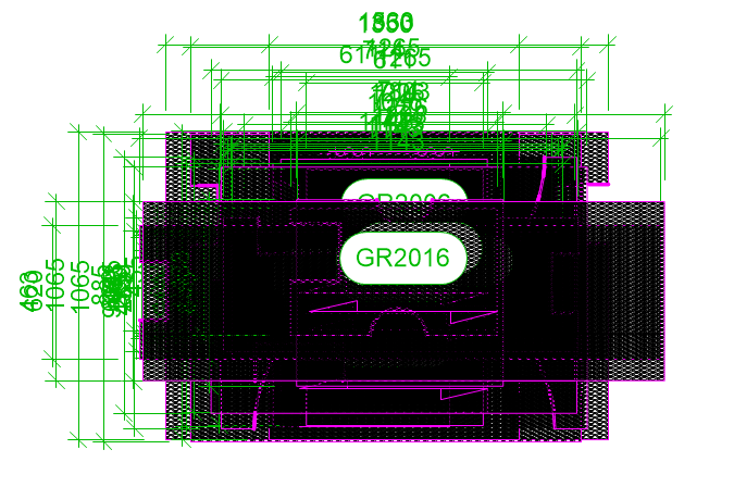
My problem is that I have created a tile and I use it to represent a product.
If I create a 2D shape and another within, then I subtract solids and then tile it, after exporting to .dwg, the cutout does not appear (as below left).
However, if I have no fill or a pattern fill, it does work (as below middle & right).
These pictures are from AutoCad after the export to .dwg
-
Hi,
There was one version of 2024 in which, when a viewport was created, it's location was in a similar location to the Sheets Layer.
ie. In my case I draw a frame around the viewport area that I want to create as a viewport. For every version except one (can't remember which one), the viewports all end up in the middle of the Sheet Layer and on top of each other. However, in one version, I remember being surprised that the first viewport was next to the second viewport, just as I had them on the Desing Layer.
Mistake or not, it was very handy.
Like this ....
Not this ....
-
Not sure how VW would approach this one, but AutoCad seems to be able to do it.
When I draw something on the Design Layer, and I create a viewport, when I move something on the Design Layer, the viewport does not show as it originally did.
eg. What was on the viewport .... What is on the viewport after I move the something on the Design Layer
I move this left object -100, -100 on the Design Layer
However, the object is in it's own viewport (a jigsaw piece). It is not associated with the 2nd viewport to the right. Obviously, if they were in the same viewport then I would expect this result.
Somehow, AutoCad can make viewports of individual or selected objects and when they are moved, the viewport crop moves with it/them.
This would be great to see in VW.
-
1
-
-
Hi,
As far as I am aware, Vectorscript can't print a worksheet to a pre-defined filename - I'm printing to the "Microsoft Print to PDF" printer.
Therefore, can anyone come up with an idea to copy text to the Windows clipboard so that it can be pasted into the filename box when printing it?
With VS's "Print ('Worksheet Name')", Windows saving convention pops up, but the filename is blank.
Since I already have files of the suffix format that I want, I would just click on an existing file and that would prefill the blank filename area, and then I want to paste in the prefix.
eg. suffix = "This file.pdf", prefix = "Despatch List ", result = "Despatch list This file.pdf"


VW2024 SP6 drag and drop
in Troubleshooting
Posted
Another day. I tried the import and ungrouping. It worked today so not sure what happened after the update.
However, I still can drag and drop any files after the SP6 update.
This is a problem because I often drop multiple PDF, DWG & IFC files to open/import them.
I'm not keen to update my other PC if it's going to be the same. However that is Windows 10 and this one is Windows 11 - which did work in SP5