Search the Community
Showing results for tags 'vertical'.
Found 4 results
-
I am trying to get radial vertical contours and my network made it, but despite the contours are created, I am not able to do anything with them because the contour node shows 0 as output... modelo-2.vwx
-

Automatic Camera Vertical Tilt Correction
martinfdc posted a question in Wishlist - Feature and Content Requests
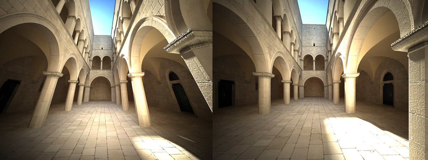
Hi, It would be very useful that the Vectorworks camera would have a feature that allows one to make sure that all vertical lines are vertical. Similar to what a perspective correction lens does in a real camera. With this new tool we could make sure that all of our renders come out with completely vertical lines and a great perspective instead of one that is deformed. It would also make things faster as one would need to fiddle less with the camera in order to get vertical lines. I attach a photo that makes clear what I'm talking about. I took the images from V-Ray for Cinema 4D Manual: http://vrayc4d.com/live/vrayforc4d-manual/vray-physical-camera/vray-physical-camera-examples/ V-Ray has automatic vertical tilt correction. Hope this gets implemented!
- 5 replies
-
- 7
-

-
- camera
- renderworks
- (and 3 more)
-
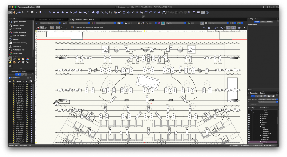
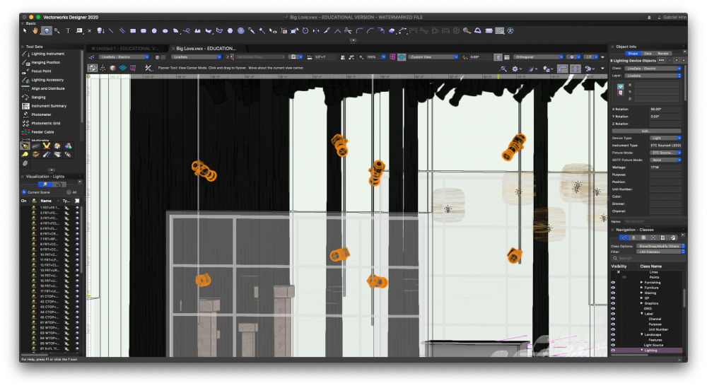
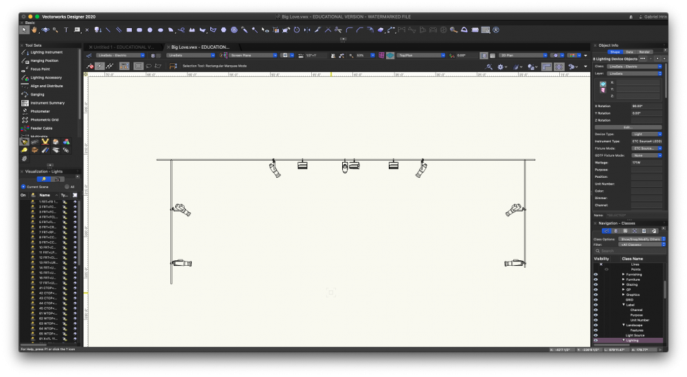
Hello Vworks World! Hope everyone is doing well in Covid times! The Vectorworks University programs have been amazing to check out during our mandatory home time. So, I am struggling with with a combination of Industry standard practices of having a "callout" style deck plot and drafting in 3D. In the show that I'm doing, I have 4 tail downs from 2 line sets at varying depths, and 2 Lustr Series 2 on each tail down. The goal was to render and test my beams in the plot, as well as create a 3d accurate version of the theatre, but my professor is now showing that what I need to do for clarity and data is create a deck plot using callout boxes in a separate design layer that shows *vertically* where they're being hung on the pipe, as well as all of the data that goes with each instrument (purpose, Channel, and Unit #). In my circumstances, I also have to be careful to not have 2 instruments representing the same data, because I'm using the Lightwright 6 Data exchange system. How on earth do I either A: create a movable section view of just the tail down and get the data properly transposed on it with text boxes. or B :have multiple symbols (2d and 3d) representing the same instrument, without repeating the data in the LW6 data. I really like having the 3d lights in the space, as I'm using a live section viewport for the whole drawing, and testing the beams was so helpful, I would hate to just delete it for a footprint. Please let me know if anyone knows anything about this, or if this is just wishful thinking! I've attached a few images to help! -Hrindous
-
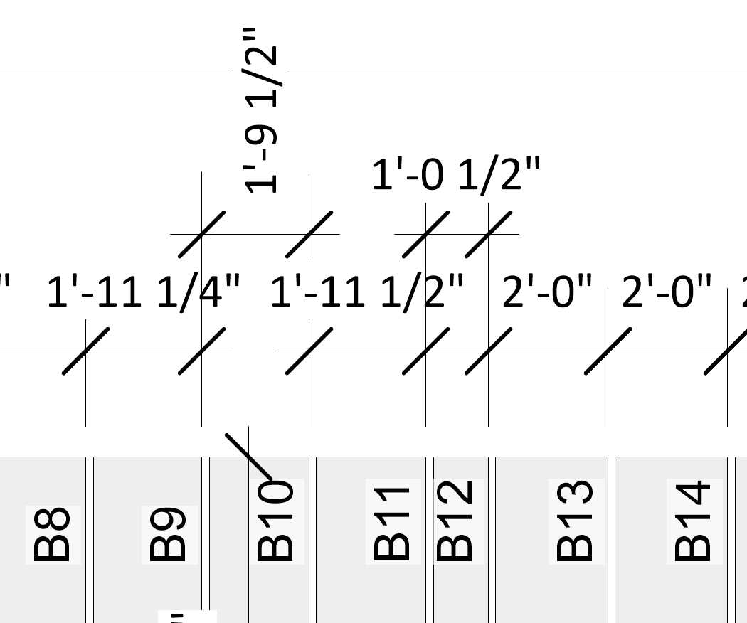
I have a lot of tight dimensions and just want to turn the text within the dimension by 90° as seen in attached jpg. (1'-9 1/2" dimension shown is not a solution but a very slow workaround) It seems like this should be somewhere within VW...? Am I missing something?