


DCarpenter
-
Posts
111 -
Joined
-
Last visited
Content Type
Profiles
Forums
Events
Articles
Marionette
Store
Posts posted by DCarpenter
-
-
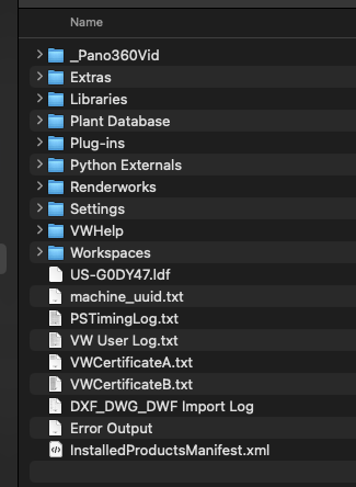
When transferring files over to a new computer I move the Plug-ins, Library, and Workspaces folder over but don't usually pay much attention to the TXT files at the root directory of the User Folder. I would like to find where my custom page sizes are kept in my User Folder but am stuck trying to find where that info is stored. Is that info in those TXT files in the User Folder root directory?
Dave
-
That is crazy helpful, thank you. I never would have thought of looking at SetEntityMatrix. Thank you so much.
Dave
-
 1
1
-
-
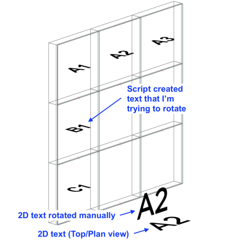
See attached for clarity. I'm trying to figure out how to 3D rotate a string of text within the script. Rotate3D, Set3DRot, and SetRot3D doesn't work on the text unless I convert the text to a 3D object which I'm trying to avoid. Not sure if I have to flip my working plane first and then create it? I'm hoping I can avoid that. Hoping someone out there might know a command I haven't tried yet.
-
On 6/25/2023 at 8:00 PM, Pat Stanford said:
The forum parser would not let me post what I wanted.)
Pat, Thank you as always. I've always appreciated your help especially when I hit road blocks like this. I will look for examples of using a number pointer and use of an offset, and let you know if i have any questions.
Did you get a citation from the Forum Police?
Posting
governmentVectorworks documents or something? -
I’m writing a vectorscript, and I need to label multiple objects in a grid (an LED wall to be exact), so my labels would be: A1, A2, A3…, B1, B2, B3… etc. sequencing numbers is easy, but how do I sequence letters? Is it possible to convert a letter to a number and sequence that way?
Dave
-
I believe I could get that program written for Unreal, but was hoping I could stick with Twinmotion and it's connection with VW.
I'm a big fan of Pat Stanford. I'll look for a forum on the Epic side of things and see what they can offer.
Thanks,
Dave
-
Yeah, I know I could go through and replace the individual symbols separately, but that would take time. Looking for an automated solution like the material substitution within the import process of Twinmotion, but for symbols. I know I'm still a novice with Twinmotion, just trying to find solutions to minimize our time spent preparing a file, so we can focus on creating an awesome render.
-
Long time VW user / script writer, and very novice Twinmotion user.
Curious question that I hope isn’t to much of a bother. I’m curious if I have the ability to write a script/program in Twinmotion to substitute imported Vectorworks symbols with Twinmotion symbols from its internal library or user library. My current VW symbol library doesn’t have any materials attached to its 3D components so using the functionality to substitute materials during the import process within Twinmotion isn’t very helpful. I’m hoping I can write a simple script to substitute symbols but don’t know if I have that kind of access or functionality within Twinmotion to do that. Hoping someone might be able to offer some clarification to help guide my search in working Twinmotion into my workflow.
Dave
-
- Popular Post
- Popular Post
Oh Vectorworks why do you treat me like this?! I like the new you v2022, but when we spend time together it just feels like things takes a lot longer than it should. I know we've been together for a long time, and don't get me wrong, we've had a great time and done a lot together, but I just want you to know that I feel like there's this distance between us that's making our relationship linger. Here's hoping for days of old when you were younger and had more energy.
Reluctantly yours,
Dave-
2
-
 1
1
-
 2
2
-
Should I report this bug?
Where do I do that?
Dave
-
Pat,
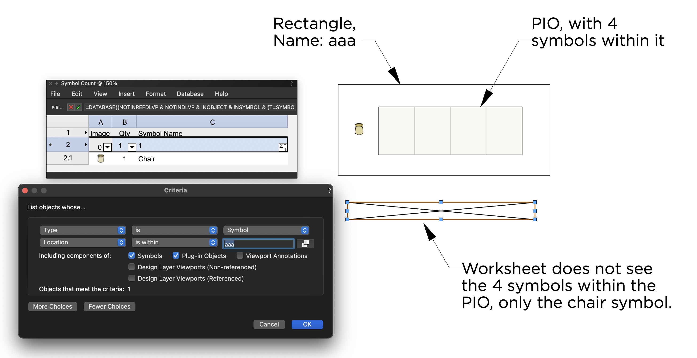
I'm not sure I completely understand what your asking. The PIO retrieves symbols from a symbol file and places them in the correct order within the PIO. If I eliminate the rectangle "aaa", the worksheet works as expected, but as soon as I use the "Location" criteria, it freaks out. I makes me wonder if the worksheet is using the coordinates of the insertions points within the PIO, verses their real world coordinates in the drawing. Not sure, but thank you for looking at it.
Dave
-
See attached image to better understand what I'm describing. I have on my drawing a PIO that places 4 symbols next to each other, and a Symbol called "Chair", all located within a rectangle called "aaa". When running a worksheet of all the symbols within the rectangle called "aaa", it is unable to see that the 4 symbols within the PIO. Can you help me understand what is happening and how to fix it? Attached is a screenshot for reference and the VW file.
Thank you in advance. I always appreciate the help I get here.
Dave

-
WOW!! I feel like I got the "A" team jumping on this, and so interesting to see how each of you would tackle this issue. I like the way Julian came at my problem so I took his code and revised it a bit to meet my needs. It still needs to be refined a bit but it does what I need it to do for now. I probably lost hours of time trying to figure out which selection procedures to use between the Selection class and the Document List Handling class. The code you all shared with me was super helpful with helping me steer my thoughts and direction. Thank you all for offering your help. The three of you are the pillars of this Forum.
I wrote this code because sometimes I get DWG files where the end points of lines to exactly match, so when I use the 2D polygon, paint bucket, tool, I'm unable to fill different cavities quickly. So I figured a quick little script to extend all the lines 2" in either direction should do the trick, and then when I was done, I could use the same tool to restore everything back to normal.
Dave
PROCEDURE IncreaseLength;
VAR
h1 : HANDLE;
i,k: INTEGER;
rCenterX, rCenterY : REAL;
rScaleFactor : REAL;
rExistLen, rNewLen : REAL;
MyH: DYNARRAY [] OF HANDLE;
BEGIN
SelectObj(T=2);
i:=NumSObj(ActLayer);
ALLOCATE MyH[1..i];
h1:=FSActLayer;
FOR k:=1 TO i DO BEGIN
MyH[k]:=h1;
h1:=NextSObj(h1);
END;
DSelectAll;rNewLen := RealDialog('Length increase:','2');
k:=1;
WHILE (k <= i) & (i <> 0)DO BEGIN
HCenter(MyH[k], rCenterX, rCenterY);
rExistLen := HLength(MyH[k]);
rScaleFactor := (rExistLen+rNewLen) / rExistLen;
SetSelect(MyH[k]);
Scale(rScaleFactor, rScaleFactor);
DSelectAll;
k:=k+1;
END;
END;
Run(IncreaseLength);
-
Thank you for the clarity. I was hoping there was a way of selecting the center of the line and then changing it's length like I can do in the OIP manually, without doing all the math, but I guess not. Bummer. HScale might work for me though. Thank you once again.
Dave
-
I've created a PIO that selects all the lines from the visible layer on the drawing. Now I simple want to increase each line's length by 2" (user defined), from it's center. How do I make sure it's length changes from it's center?
Dave
-
Pat,
Bummer, but thank you for your alternative solution. Trying to make it as simple as possible in order to safeguard it from being messed up by the end user. Your suggestion got me thinking about another possibility. Thankful for your prompt reply and accessibility.
Dave
-
I'm stuck,
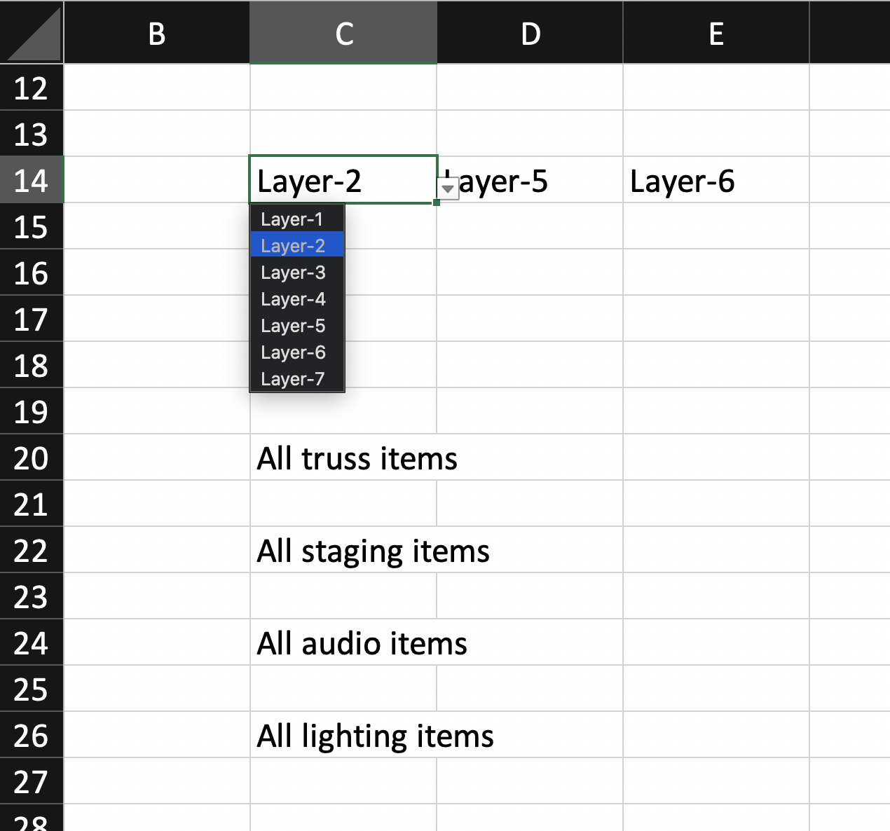
See attached Excel worksheet image for clarification of what I'm trying to do in VW. I've created a worksheet in Vectorworks with four different database rows in it. Each database row calculates, summarize, and displays information in a different layout than the others, but the one thing they have in common is that they all get their information from the same three layers in the VW drawing. What I'd like to do is create one place (C14,D14, and E14 in attached image) that can determine what layers are used in the four databases (rows 20, 22, 24, and 26), so the user doesn't have to edit the criteria for each database. Is that possible?
In excel I can create a cell that has a pull-down list of values the user can choose from. If it's possible, I would love to do that in the VW worksheet where the pull down is a list of the layers in the VW document, then each database row would reference those cells to determine which layers to look at. I am comfortable writing my own script if that's helpful, but am hoping there's an easier way to do this within the worksheets.
Any thoughts?

-
ok, thanks. Yes, I found a really great script someone posted a few years ago that really help.
Thank you.
-
wow, that would make sense. This is my first time creating an event enabled script. Do I have to move entire script into Event 3? Is this a general rule of thumb when working with event enabled scripts?
-
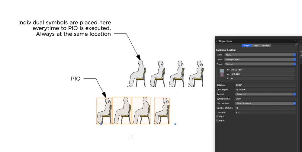
So I've created a simple script that duplicates a selected symbol from a pop-up window. I've also added an event script that changes the "Distance" parameter based on the symbol selected. Developer mode is 'off', but I don't understand why when the PIO is executed that it creates a second set of symbols outside of the PIO. That second set of symbols are always in the exact same location in every drawing, regardless of where the PIO is. I've attached a screen shot if it's helpful. Any ideas why?
-
SetName() and the Batch Rename tool are exactly what i needed. I remembered seeing that batch rename tool in the highlight reel for 2020 but could never figure out where it was. I kept on looking for it in the Organization window for layers and classes, but now that i know where it is, it's like a whole new day!
Thank you for your help,
Dave
-
Julian,
According to the description of the SetSymbolOptionsN(), it only sets the insertion options and class of the symbol.
Dave
-
Writing a simple script to add a prefix to all the symbol names in the drawing but can't seem to find the command to replace the current name with a new name. I can get a handle to each symbol in the drawing and its name, but can't figure out the command to write a new name for the symbol? thoughts?
H1:=FInSymDef(H1); {will get me the handle to the first symbol in the drawing}
SymName:=GetSDName(H1); {will get me the current name of the symbol}
current symbol name: "Toilet"
symbol name after the script is run: "Toilet-1"
-
UGH! Thank you for your help. I was in the VS:Function_Reference doc but was looking under Layer section. I couldn't figure it out because that's the only place I could imagine it would be.
Thanks Pat.


Graphic Legend - Summarizing items
in General Discussion
Posted
Newbie question about Graphic Legends, see attached. I've created a Graphic Legend to summarized symbols in a viewport according to a unique record that is attached to each object. I love the way it summarizes each symbol and gives me a total count for each, but for PIO objects (Soft Goods, Video Screen, Rope and Stanchion) it itemizes them instead of summarizing them. Not sure I understand Graphic Legends enough to figure out where the problem is so I'm hoping someone else might have a solutions. VWX file attached if that's more helpful.
Thank you for your time,
Dave
Example3.vwx