


CipesDesign
-
Posts
5,153 -
Joined
-
Last visited
Content Type
Profiles
Forums
Events
Articles
Marionette
Store
Posts posted by CipesDesign
-
-
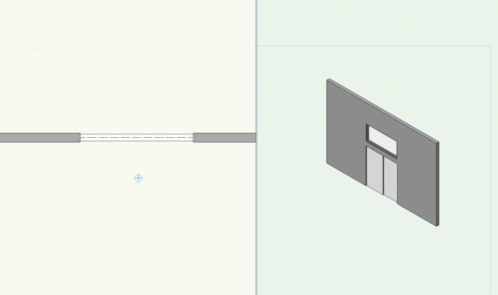
I do not see this problem. First, I inserted a door. Then I inserted a clerestory window, but off to the side, not directly above the door. Then I disabled Wall Insertion Mode and dragged the clerestory into place above the door. See attached for result.
Perhaps you accidentally ended up with a door and/or window that are not "In Wall" (ie: properly inserted)??
-
The Surface Hatches feature has always behaved really badly (and I have complained and filed bugs). Here's hoping the engineers make fixing these flaws a priority.
-
 2
2
-
-
I don't disagree. However sometimes all I want is a quick (read: single mouse action) way to get there. And although Line Styles do add capabilities, they require way too many mouse actions for this simple example. User choice should be paramount. In an ideal world...
-
To my knowledge there is not. I also miss the ease if the older UI in this regard. There are now way more mouse clicks and scrolls required to select a simple dashed line. It would be ideal if the user were able to choose (but I'm not holding my breath).
-
Knowing that a Framing Member derives its 'length' from the center of the object, you could create a formula in your worksheet to calculate the additional length of the angled end, thereby resulting in a "total length" column in the report.
Or, you could create a Section VP (Profile) of the Member and place accurate dimensions in the Annotations, including total length and angle of end cut.
Personally, I prefer the second option because a picture is worth a thousand (or 5000?) words
-
Thanks Hans-Olav! I was going to list that as well, but forgot!
Techdef, Unless you need to retain geo-referenced data this is probably the easiest and best method.
-
This could be a dangerous operation. Please Save As to retain previous version as backup.
Method 1: [make sure sure all Classes are ON] Select All, then Group, for one Design Layer at a time. Move the Group and jot down the exact x/y offsets for the move. Now Select All then Group for each remaining Design Layers and move them the exact same x/y offset. Subsequently, remember to Ungroup each set (but only Ungroup once as more will destroy many parametric capabilities of "complex objects").
Method 2: [make sure sure all Classes are ON] Set Layer Options to Show/Snap/Modify Others. Select All and (Group perhaps, always somewhat safer in my opinion) Move.
Make sure to change back to Show/Snap (NOT Modify) when done. Leaving this on is recipe for boo-boos.
Method 3: [make sure sure all Classes are ON] Set Layer Options to Show/Snap/Modify Others. Select All and then Create Symbol. Warning: while this will create a movable/draggable single entity to play with, it will also place the Symbol and all building elements within it into a single Design Layer. This is not desirable for working on the building later. One workaround is to set up your file using only a single Design Layer with multiple Classes. Not really how VW's is designed/intended, but it's somewhat workable if you're diligent.
Method 3: Use Referenced Files. See the User Guide for more. Not my favorite for various reasons, but sometimes makes sense for certain projects.
I have a very rigorous methodology for Building Placement onto Site but it is too much info for this thread. Just remember that VW's is unique and you need to adhere to its basic principles.
-
I would guess that there is an actual (not a ghost) object in the file. Use your best detective skills to find it and delete it.
When you create a Floor (and other objects) there is an option to retain original geometry. So if this is enabled, even after deleting the Floor, the original object remains.
-
1
-
-
If you cut a section [perpendicular to eave] though the existing geometry (framing) then you can measure the slope/angle. The you can apply this angle to the Roof Face.
-
Nice work! (I have never loved the UI on the Stair Tool so I lose patience with it pretty quickly)
-
You can create it with the Stair Tool (I think), but not with the rounded corner. That will need to be masked with a polygon or round wall, or some other contrivance. Also, not sure whether the current Stair Tool will allow zero width winder treads as you show; I would need to try it/fiddle with it. Often in these cases (curved & zero width winders, eg) I find it way faster and easier to work with simple extruded forms: Draw each windered tread in 2d; extrude each one and place at the correct height. Then use two separate straight runs of Stair for the lower and upper portions. Yes, you will need to do some math, but that's why they call it work. One trick is to use a dummy stair just to find the height of each riser. That will speed things up a bit.
-
There are a couple ways to do/fake this. One is to let the winders be square and then cover the corner with a curve. Or you could use different pieces for each run. Or use a straight stair at the bottom and top and extrudes for the winders. One note, to my knowledge the stair you show will not meet code (US); as I recall the minimum width for tread is 4". But perhaps this is for stage and so does not need to meet code?
-
Thanks Wes! Especially love the drawing title😁
-
If I remember correctly this is a flaw (Stairs not recognized as Structural object?). If that’s the case then you maybe need to use black polygons in annotations to create desired look. Try setting the polygon tool to inner boundary. If it works it should be pretty fast.
-
I have recently seen same (or similar) behavior where the lines of a Hatch, in a hatched, layer-plane polygon, which is at Z=0 show on top of other objects which are above Z=0. In my opinion this is unwanted, buggy behavior.
-
In my opinion VW's needs to show actual fonts in the font pulldown selection menus. It is ridiculous for the user to open another document (no, another application!) just to see what any given font looks like. This has been on the wishlist for a long time, so I am giving it a little bump.
-
I don't think this is currently possible. You can maybe Ungroup and edit the pieces, but that is probably not a good solution as the road will lose all parametric abilities. Or, maybe duplicate the road, change the curb to 600 then Ungroup only the duplicate and remove all the other pieces? Then at least you have the parametric road to fall back on should you need to make changes...
-
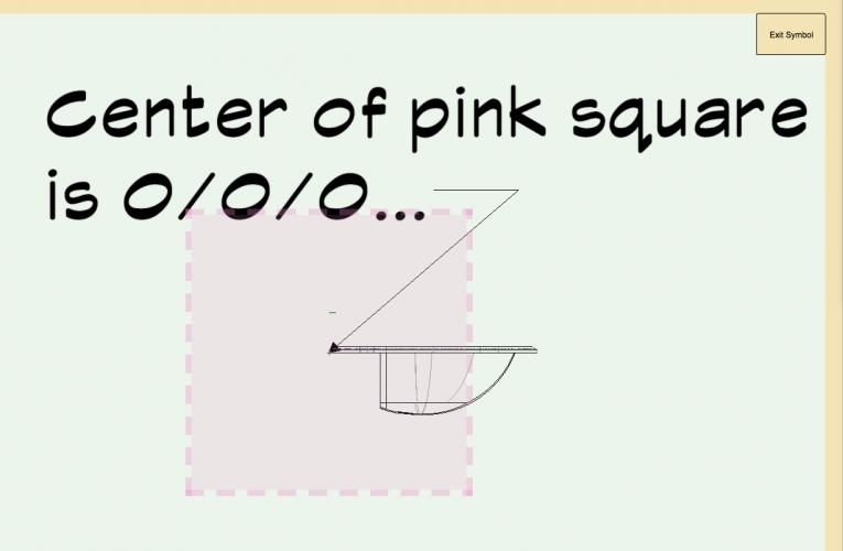
Why fight this kind of uphill battle? Just edit your symbol so that your desired Z=0 is aligned with the zero mark (locus) in front or side view and get on with it. See attached.
-
Just a guess, but probably the inner mind of VW's uses a symbol's settings as the zero point. For example, when I place a new Sink from the libraries, zero is equal to the bottom of the flange which would sit on a counter top, or about an inch below the sink's highest point. Therefore, if I want the sink to sit on a 30" vanity all I need to do is move up Z=30" and the flange will align as expected. And, if I Edit 3d for the sink I find the Z=0 locus right at that same level. Try it and see what you think.
-
Yes. Use the "Align Stations Vertically". Again, expect some trial and error. See the user guide here: http://app-help.vectorworks.net/2019/eng/index.htm#t=VW2019_Guide%2FSiteModel1%2FCreating_NURBS_Roadways.htm&rhsearch=curbs road&rhhlterm=curbs road&rhsyns= and other items regarding Nurbs Roadway
-
I have had that happen before. Frightening😫. There are three (I think) toggle modes in the reshape. You need to make sure that the movement is constrained to the x and y axes. Better yet, and because of this, I stopped trying to make those sorts of adjustments by mouse action and instead type in the numbers I need. I even usually resort to going back a couple steps, to the original polyline (saved off to the side). Duplicate, make needed corrections in 2d, then re-create road. Then I go vertex by vertex as needed to adjust grades. It's trial and error (at least for me) and sometimes takes three times to get it how I want it, but it's SO much better than old school by hand method. And once it's right, bob's your uncle.
-
Make sure that "Vertex Only" is selected in the little pulldown?
-
Also, can you explain exactly how you are "importing" the house model? File to file copy and paste? Referencing? Other?
-
I totally agree. If you have time you can file a Wishlist Item.


Complex Window
in Architecture
Posted
Do as Taproot suggest above, and I would add that once you create one window with the correct slope you can duplicate it and simply change the height and elevation. You can also create windows on one side of the wall (left or right) and then use the mirror tool (in top/plan view) to duplicate it to the opposite side, using the ridge/center as the mirror point.
As a note, it would be good if VW's Windows (and Doors) allowed for a Pitch or angle instead of just using Rise. However if you're willing to do a little math and a little trial and error it's not terribly difficult to achieve your goal.