
Michael Siggers
-
Posts
125 -
Joined
-
Last visited
Content Type
Profiles
Forums
Events
Articles
Marionette
Store
Everything posted by Michael Siggers
-
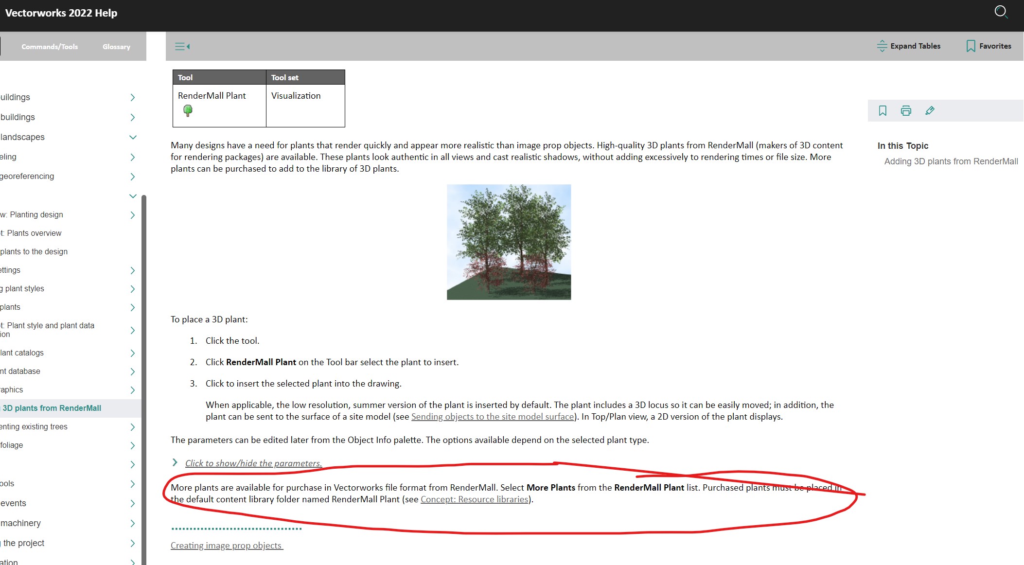
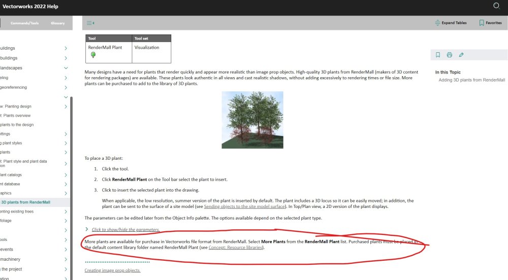
Hi I've been looking at the Rendermall Trees and wanted to add some more. The attached screenshot is from Vectorworks Help for Vectorworks 2022. It states that at the bottom of the list of trees/plants is an option for 'More Plants' to purchase well, more trees and plants. In Vectorworks 2023 Architect, I do not have this option available. There is no 'More Plants' Option at the bottom of the list. I'm assuming this has been removed in Vectorworks 2023? If so, how do I add more Rendermall Trees/Plants? Kind regards Mike
-

Cricket Lane Mat Modelling - Best approach
Michael Siggers replied to Michael Siggers's topic in General Discussion
Hi @jeff prince Would be interested to know; How the Carpet texture can be mapped on the top to be the correct width, and How this appears in Top/Plan view. Mike -
Cricket Lane Mat Modelling - Best approach
Michael Siggers replied to Michael Siggers's topic in General Discussion
Hi @jeff prince Definitely something I will explore as, like you say, this can also be used for the substrate. MIke -
Cricket Lane Mat Modelling - Best approach
Michael Siggers replied to Michael Siggers's topic in General Discussion
And @Elite Exhibits It works perfectly in Lumion 🙂 Mike -
Cricket Lane Mat Modelling - Best approach
Michael Siggers replied to Michael Siggers's topic in General Discussion
Hi @Elite Exhibits This works a treat, thank you so much. So, it seams, assemble the layout in 2D, with the textures in the correct places and the white lines. Have to admit, I did not think you could group the 2D objects. Then, create the 3D version. I have experimented and had no problem applying your image to the top face of the 3D element. Once again, thank you so much for this. I'll start going through the various Carpet versions and create a library for use, working through your instructions. Kind regards Mike -
Cricket Lane Mat Modelling - Best approach
Michael Siggers replied to Michael Siggers's topic in General Discussion
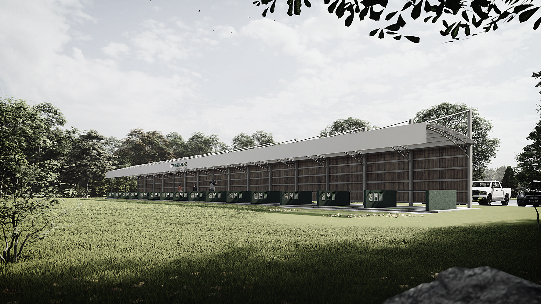
Hi @jeff prince This is actually one piece of Carpet 3.65m wide with the different finishes woven into it, so the edge banding, central banding, and lines are all woven into one piece of 'carpet'. Kind of like a high end Astroturf. The length can vary but is typically above 30m. As well as longitudinal three lines, there are also lines to mark the Cricket Creases, where the stumps are located. I have attached an example. The high end facilities can have 10 lanes all next to each other, some with training lines and others not, all covered by a steel canopy with lighting. Also, tested my previous attempt and it did not work in Lumion. I may try importing one from Sketchup and seeing how that works. Mike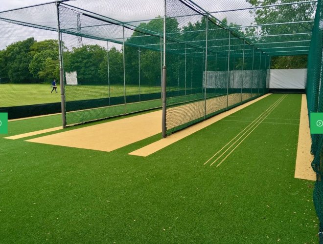
-
Cricket Lane Mat Modelling - Best approach
Michael Siggers replied to Michael Siggers's topic in General Discussion
Thank you @Tom W. and @Pat Stanford I think I have done a sort of variation on the Nurbs proposal. I created a 9mm thick solid, then added 2D Polygons on top, with no gap, assigned to Classes with Image Fills. Created a Symbol, but I suppose technically it has no 2D element. I've attached the file and would appreciate your comments. This seems to work though as the finish shows up in both Plan and 3D Views. Although the file size seems quite large for a simple carpet, but I guess that is down to the image fills. These were ones chosen from Vectorworks, so I suppose I could find some image fills which are not so large file size wise. Mike 2012403163_Practice9-ECBCarpet.vwx -
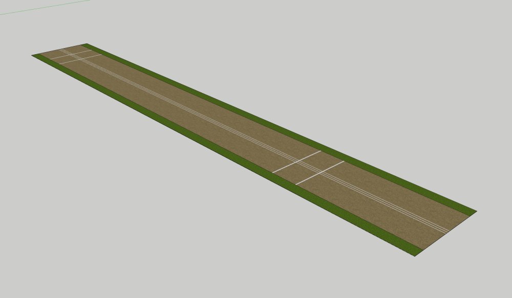
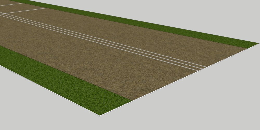
Hi Another question on my long journey to mastering Vectorworks 🙂 Attached are a couple of images showing a Cricket Lane which, over the last 5 - 6 years I have been modelling in Sketchup. I am slowly replacing Sketchup with Vectorworks as my main Software and so far, so good. So, hopefully a simple question. This 'Mat' is 9mm thick and as can be seen, the surface is divided up into different finishes, including such elements as the three Training Lines. It has to have a thickness as it is also shown in sections along with the various supporting substrates. In Sketchup, the entire Mat is one object/solid with the top surface divided and then different textures added. The $64000 question is, what would be the best way of modelling this in Vectorworks? I can create a divided Flat surface with no thickness, but what would be the best way of creating this solid, with various textures on the top? As well as being used in the drawings, the model is then exported to Lumion for Visuals, so it is shown in 3D views as well as Plans. I did think of using a Hybrid 2D/3D Symbol, but then the 2D Texture would not show in 3D. Or, I thought I could model each bit as a separate solid and then group them, but that seems rather tedious. Any thoughts would be greatly appreciated. Kind regards Mike
-
Snapping to objects on different Layer
Michael Siggers replied to Michael Siggers's topic in General Discussion
Yes, does seem like an odd setting, to effectively turn off all other Snapping points outside of the plane being drawn on. Mike -
Snapping to objects on different Layer
Michael Siggers replied to Michael Siggers's topic in General Discussion
Now that I have disabled the 'Ignore Non-planar snaps in Planar Context' setting, it is working a treat. I can draw on the desired plane while snapping to items on other planes. Think I have now solved my issue. Mike -
Snapping to objects on different Layer
Michael Siggers replied to Michael Siggers's topic in General Discussion
Think I may have found the cause. Found a setting in Snap Settings, 'Ignore Non-Planer Snaps in Planer Context'. Unticked this box and I think, just think I may have solved it. Mike -
Snapping to objects on different Layer
Michael Siggers replied to Michael Siggers's topic in General Discussion
I really can not get it to work. Pretty sure I have tried every setting. Even tried converting the top object to a Generic Solid and that made no difference. Mike -
Snapping to objects on different Layer
Michael Siggers replied to Michael Siggers's topic in General Discussion
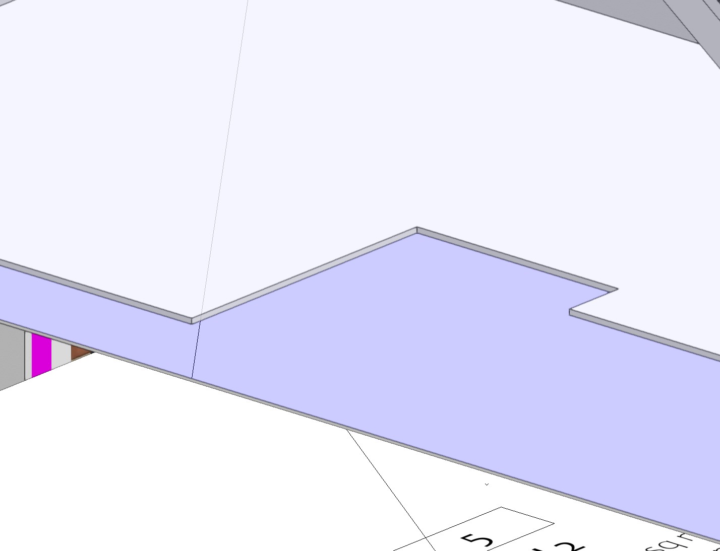
HI @zoomer and @Tom W. Tried with Automatic Working Place enabled and disabled. I've attached a simple file, which has two objects, one above the other and on different Design Layers. The large cut out section I created in the top object, then switched layers to the lower object, and the only way I could 'trace' the cutout in the top was to use a 3D polygon. I have created another cutout in the top so would appreciate your thoughts on 'tracing' this to the lower object. Snapping does not work when using 2D Polygons and lines. And........ the circle......... The only way I can do this is to set the lower object Design Layer active, then use Plan view (0), to drawing a matching circle, although when I do the extrude as part of the circle command, it does not automatically subtract from the object. It's the little things like this that are frustrating me at the moment, and simple operations are taking longer than I think they should. Mike Snapping.vwx -
Snapping to objects on different Layer
Michael Siggers replied to Michael Siggers's topic in General Discussion
Hi @zoomer So, I've repeatedly tried drawing in a 3D view, referencing snap points on the object above, and the only way I can do it is to use a 3D Polygon. If I tried to use normal lines, rectangles, or polygons, snapping to the object above on a different design layer does not work. Mike -
Snapping to objects on different Layer
Michael Siggers replied to Michael Siggers's topic in General Discussion
Hi @E|FA Yes, all the same scale. I have since found that it does snap if I use a 3D Polygon to draw on the surface of the lower object, when in 3D view. Does not seem to work/snap when using 2D tools, (lines and polygons). Now to figure out how to show Velux Windows as Dashed lines on floorplan 🙂 Mike -
Hi This is one of the things that is annoying me about Vectorworks at the moment. I am trying to cut out a shape in one object on a layer. I have already cut the shape out of the object above which is on a different Layer. For the life of me, it will not snap to the object above. It will snap to the first pint, which I can use to line up the starting point, but I can not then snap to any of the pother points in the shape above. Frustrating as the time it has taken me to type this, I should have been able to do this. Why can I not snap to objects on different layers. Show/Snap to others is set for both Classes and Layers, and all snap option are on. Mike

-
Sectional Hatch Issue - On Sketchup File Import
Michael Siggers replied to Michael Siggers's topic in General Discussion
Hi @jeff prince Many thanks for the help with this. Great to get advice from someone so knowledgeable. It was exactly what you said, with the import of the Sketchup Model causing the issues. Once I knew what to look for I could fix the issue and it now works perfectly. Essentially, it had split some of the nested groups into groups containing a Mesh and a 3D Polygon. Once I spotted it, it took no time to fix. Was great learning experience too with enabling and disabling multiple selection mode in the OIP. In the future, I'll probably leave the Sketchup Model in its component parts and then create the Symbol in Vectorworks. See if that helps. Anyway, all good. Enjoying learning Vectorworks and slowly but surely seem to be getting to grips with it. The 3D modelling side is now speeding up. I guess that's always the case when changing from one software package to a new one. Just takes time learning different ways to do something I can rattle of in minutes in Sketchup Pro. But, practice makes perfect. Thank you again. Mike -
Sectional Hatch Issue - On Sketchup File Import
Michael Siggers posted a topic in General Discussion
Hi Once again it would be much appreciated if anyone could shed some light on the issue I am having. I created a Number of Models in Sketchup for a Project I am working on. The models, (furniture), is made up of groups and each unit has been saved in Sketchup as a Component, and allocated to a Sketchup Tag, (Layer). I imported the Model into Vectorworks and all the Sketchup Layers became Classes, as expected. So, moving on to presenting my drawing, I have to create 1:20 drawings for each piece of Furniture for the Conservation Officer. All was going swimmingly well, almost cracking open a beer.......... When I realised that the Section views were not showing the Section fill allocated in the Class for that object. Much time late, and after having tried everything, (I think I've tried everything after going through the forum), I still can not get the hatch to appear in the sections, and more specifically different hatches/colours for each element. I've tried ticking and unticking every option box, and tried Section Style, but that just places the same hatch in all objects, not what I want. Anyway, I've attached the file. I even created a bogus object on a different Design Layer and sectioned that.......... It worked perfectly, but it can also be seen that the section caught a piece of furniture, which does display the hatching chosen, this is in the examples underneath the Sheet Border. I have attached the file, and would appreciated any help on this. The only thing I can think off is its the way I have created them in Sketchup, but I am stumped, as they are all solid groups and Components. I can not seem to get the Hatch pattern selected in the Class to show for that Object/Class in the Sectional Views. Kind regards Mike 27242337_C04-2023-03-WakeGreenFurniture.vwx -
Moving Objects in 3D and locking axis of movement
Michael Siggers replied to Michael Siggers's topic in General Discussion
Hi @zoomer Yes, forgot to mention, I have restricted them to 90 degrees. Mike -
Moving Objects in 3D and locking axis of movement
Michael Siggers replied to Michael Siggers's topic in General Discussion
Many thanks for the replies. Disabling the Angle Snaps has made it a lot easier. Mike -
HI When I press the T key, it activates Trim command. Mike
-
Hi Slowly getting to grips with Vectorworks, and currently in the middle of my First Project using it. However, I am really struggling with moving objects in 3D, and constraining to either X, Y, or Z axis. The guide states to hold the Shift Key, but I can honestly say this makes no difference and does NOT lock the axis. I am used to using Sketchup where pressing one of the arrow keys locks the axis of movement. I am simply trying to move a line along the X axis so that it sits on the face of a 3D object. Some forum posts mention pressing the 'T' key to lock the axis, but this activates the Trim command. Any help would be appreciated. It's these little things which frustrate me. Mike
-
Hi Is it possible to resize the Border /Title Block Symbol and remove the double lines around the edge? So, attached is a file which shows my Title Block/Border. This is A1 size for A1 paper. However, when I print this, my printer always has to crop it due to Margins. Therefore, in an ideal world I would like to resize this so that the size of the Border/Title Block is slightly under A1 size. When I edit the Title Block Layout, it is not possible to select the Double lines around the edge and resize them. Is there a way to do this, to effectively make the total size slightly less than A1? I can increase the Title Block Margin sizes all round in the Title Block Settings, which relocates the Inner line further in. Is there a way of getting rid of the outer surround line? Kind regards Mike A1 Border Query.vwx
-
Hi @Tom W. Ah, yes, thank you. I have been playing with that setting. Good to know that different Section Styles, (Classes?) can be used for the Merged ones. Mike
-
Thank you @Kevin K Yes, I have been having some Zoom tutorials through the company I purchased from and they've been really helpful. My approach has been to reproduce a project I have already completed in the past and then use that in the Zoom meeting. It's been really good. I guess the thing is just learning how to do what I previously used to do but in a different Software package. Its also getting used to where everything is, tools, settings, menus etc. I'm enjoying the learning and as with when I learnt AutoCAD, (before the beginning of time), the more I use the software the better. The 3D side of things is not a problem as I've been producing all my work in 3D for years, it's just transferring those skills to Vectorworks. It's also inspiring when I see examples like the work you have produced. Mike