

Peter Neufeld.
-
Posts
337 -
Joined
-
Last visited
Content Type
Profiles
Forums
Events
Articles
Marionette
Store
Posts posted by Peter Neufeld.
-
-
Yes excellent point.
Just a bit over 1mm from a 10º bend in my example (3m long bench). Which you might get away with depending...
Cheers,
Peter
-
Hello,
Tom is right. Another way is to model forgetting about the curve until the end and use the Deform tool. This way the modelling is easier. You might want to save bits and pieces along the way in case you need to go back and refine because once bent an uneditable Generic Solid will be produced.
Cheers,
Peter
PS. A single Solid Addition might not be what you want so you probably need to do this a couple of times; once for the base of the bench and then the slats. Even if the slats aren't touching they can all be combined into a Solid Addition and this will make the one object available for bending.
-
 3
3
-
-
Hello,
I would also play with the 'Smoothing Angle' settings in the Background Render Settings option in the OIP. Although I would definitely follow Kevin's advice first.
Cheers,
Peter
-
1
-
-
Hello,
Here's an example of some of the Graphic Legends (GL) that we ship with the Australian version for Spotlight that show Hoists, LX bars, Bridles, Truss, Ladders and so on.
As Pat says, GLs are the way to go and very powerful.
Cheers,
Peter
-
I can't answer that I'm afraid. Now I have submitted the report if I learn anything about this I will post back here, unless some of my colleagues know the answer. I see you have tagged Tony.
Cheers,
Peter
-
1
-
-
Hi Tom,
Thanks for pointing out this observation. It looks like this stopped in v2020 and maybe the Help wasn't updated? . I will report this.
This is what it looks like in v2018:
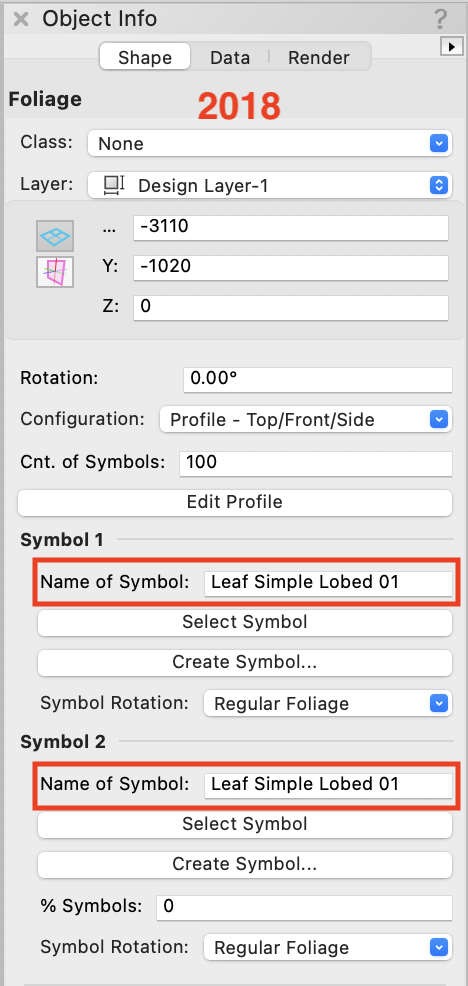
Cheers,
Peter
-
Hello,
I've been investigating this recently and just came across this thread. As we all know getting 'As-Built' 3D models is the holy grail. I recently spoke to a 3D scanning company based in Australia who said it would take maybe a day to scan for example, a 3000 seat auditorium. Including the person and the scanner that would cost AUS $2200 per day.
This particular company said they could then model everything in Autocad or Revit or Sketch Up. They added that to build a model of this 3000 seater depending on detail (how long is a piece of string?!) would cost between AUS $3000-$5000. I expect they farm this out to someone in another country. At least you would have the Point Cloud to check for accuracy afterwards and I am sure there'd be a fair bit of tidying up to do. Certainly for the level of complexity that Mark's example shows, quite a lot of extra work.The point is, forget ACAD or Revit, the best thing about this is that when importing Sketch Up models, vertical and horizontal objects get converted to Vectorworks native architectural objects (walls and floors). From the Help: "When selected, architectural objects in Vectorworks are created from SketchUp faces that are not contained in SketchUp groups of components". You obviously don't necessarily want rigging beams etc coming in as floors but that would entail a discussion before the work was done.
In effect this means that we can get Vectorworks models from third parties! I am no longer a practitioner so I have not done this in practise but I thought I'd just mention it.Cheers,
Peter
PS. The other point is that this should be the venue's responsibility and cost and not the player.
-
1
-
-
Ah I thought so!
Mark's symbols are much much better than the 2D only ones I posted. Lovely. Brings back memories of the great and some not so great (ie more recent) Strand offerings! Stick with Mark's generous offering. The 3D is wonderful.

Cheers,
Peter
-
1
-
-
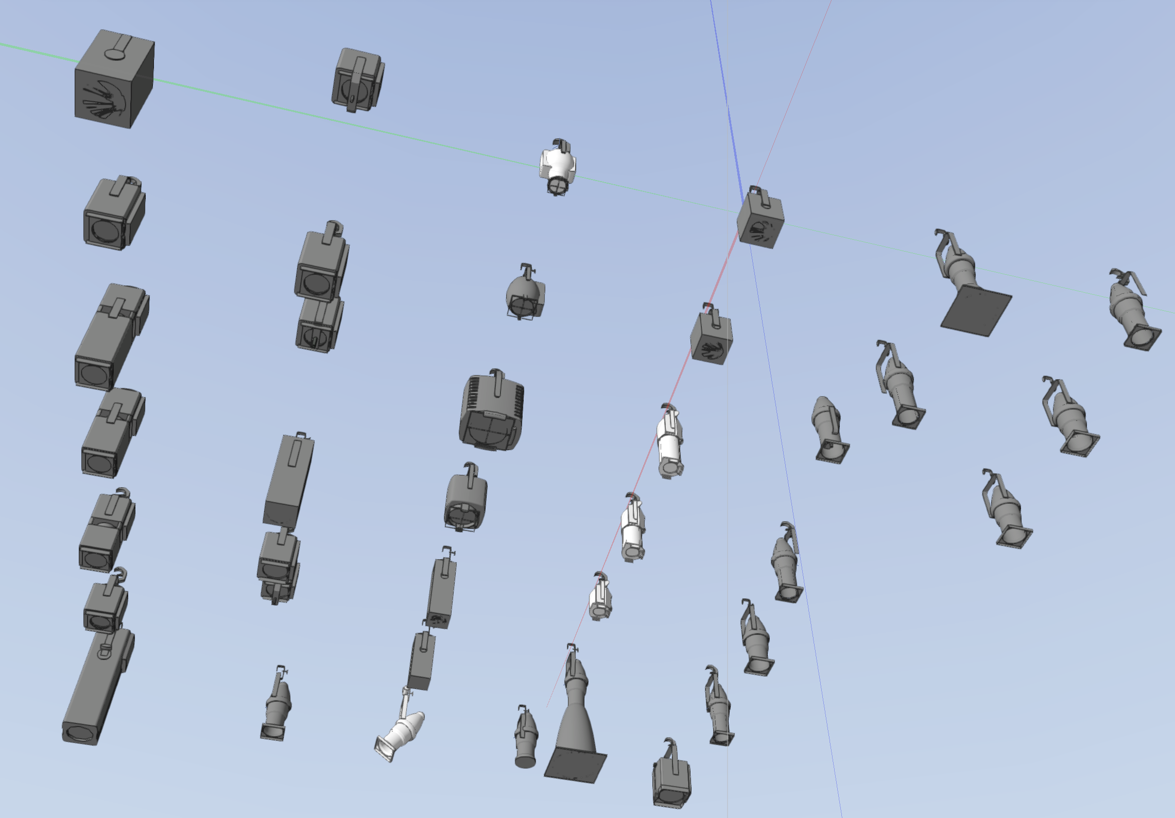
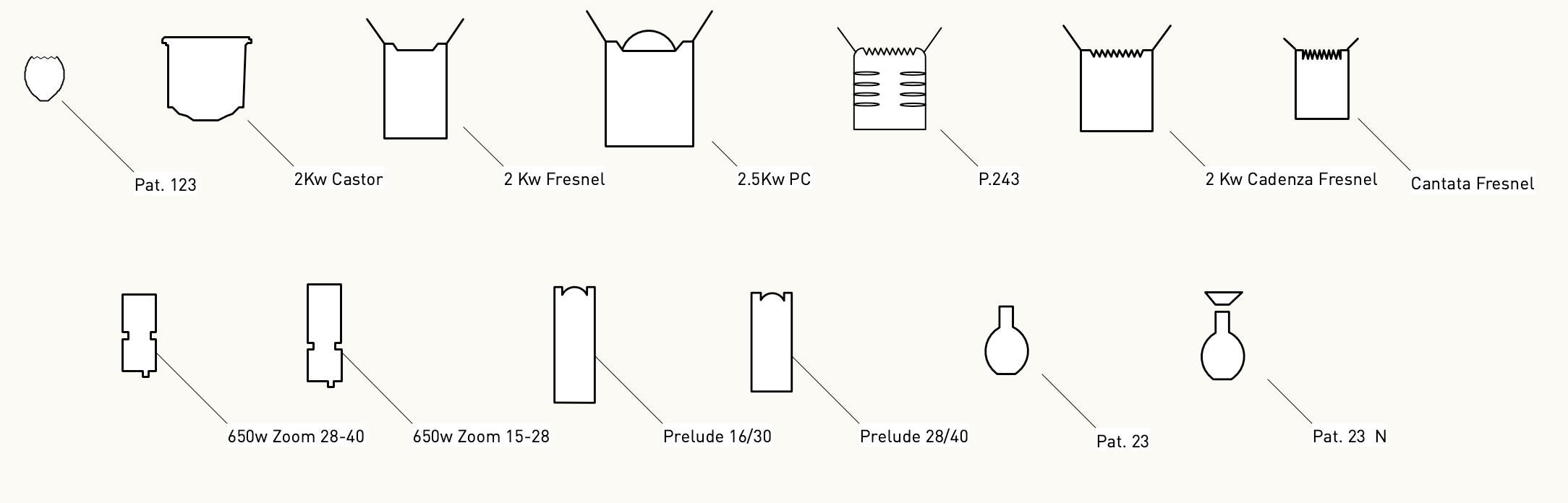
Hello,
If you want some shapes please find them in this Vectorworks file that I enclose. They're 2D only symbols, no record attached. Just do a Modify>Convert>Convert to Group to get the geometry. Then follow Justin's advice on turning them into Lighting Devices.
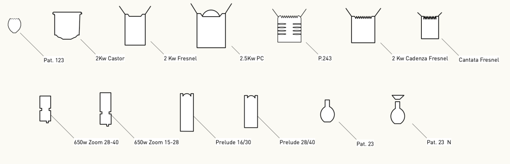
You should also check out https://www.fieldtemplate.com
Cheers,
Peter
-
1
-
-
Hello,
Enclosed are the GL's we supply for our users in Australia. Please feel free to use.
Cheers,
Peter
-
1
-
-
Hi Sam,
You make some good points. I suppose if the cable was picked up one end by a cable pick then the data tag readout would be pretty truthful but I'm no engineer. If it's just like a 'waterfall' drop to the deck off one end (as you nicely describe) then of course it is beyond what a data tag could know about. However in that case one might just add a point load. It wouldn't be that hard to work out how much a multicore with a 10m drop x a dozen others might weigh.
That's by the by. I give out this data tag simply because only Hanging Positions are able to give out the weight unlike other rigging objects and I hope it is useful for users.
Cheers,
Peter
-
Hi Sam,
Here's a quick movie:
Cheers,
Peter
-
Hi Tobi,
In case you don't know, if you right click in the empty 2D part when editing a symbol, the program will create the 2D either as a wireframe or dashed or normal Hidden Line render. Much less overhead than an autohybrid!
Cheers,
Peter
-
1
-
-
Interesting point Andy. You should do an enhancement request and it seems the precedent is already there.
The hybrid Straight and Curved truss tools can be rotated freely without any warning, likewise any hybrid symbol placed by the Truss tool. The Curved Truss and Truss objects once rotated become 3D only, and the Straight Truss maintains it's hybrid nature. Spotlight has always broken the rules!
Cheers,
Peter
-
Hello,
I give this data tag out to our users that dynamically calculates the weight of Hanging Positions. I've placed some cables on and it seems to calculate those.
Cheers,
Peter
-
1
-
-
Hello,
Check out this post from September last year. I don't know anything other than the video. This is more for straight slabs rather than free form.
You might have to DM him as the link to his site doesn't seem to work.
Cheers,
Peter
-
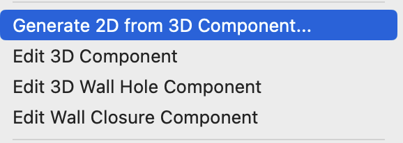
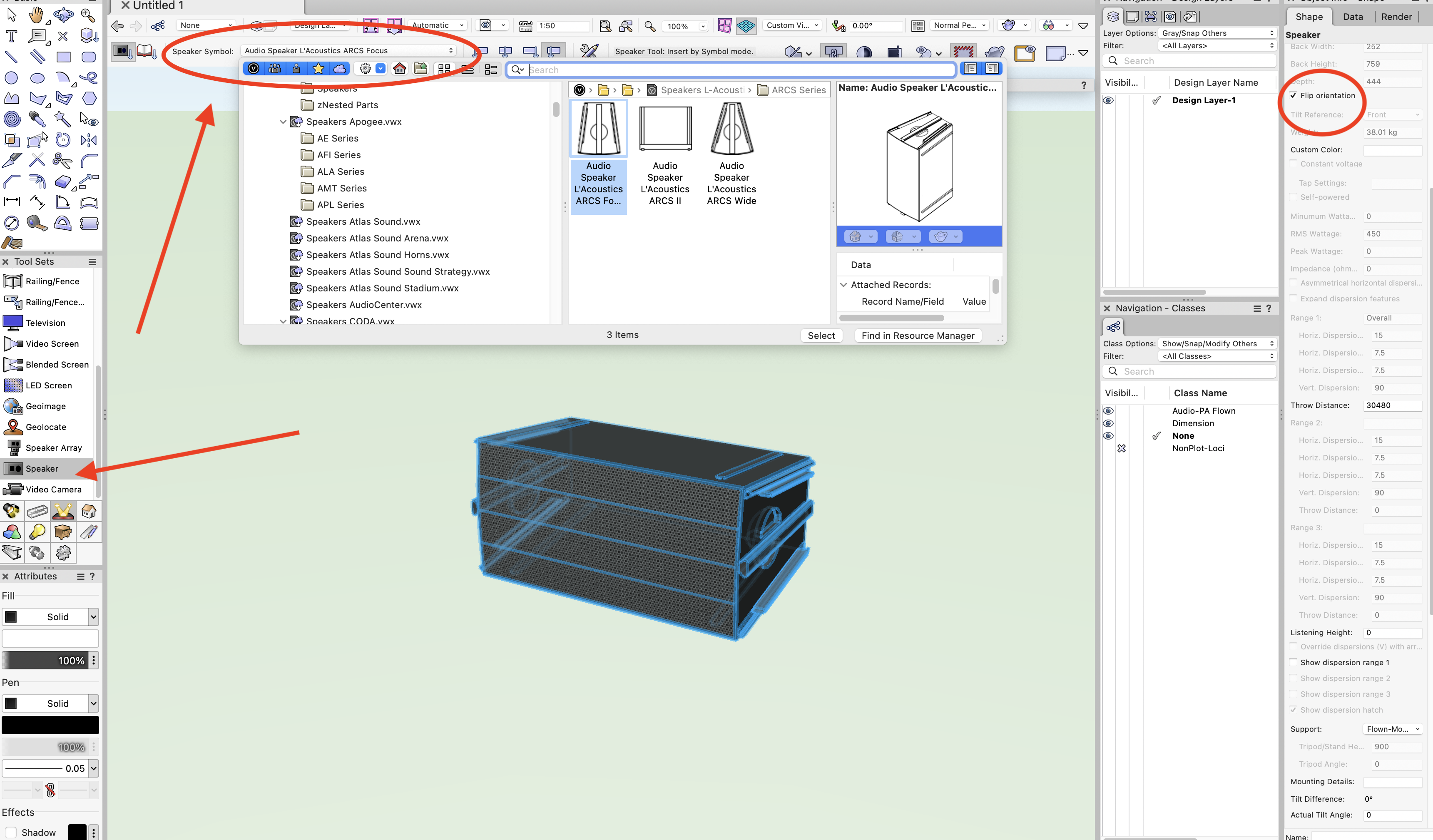
Hello,
Tom is right. However assuming that you're a Spotlight user if you want the benefits of turning that library symbol into a "higher level object" then insert it using the Speaker tool in the Events toolset. There's a flip check box and a tilt field, and of course all the other benefits of using the Speaker object.
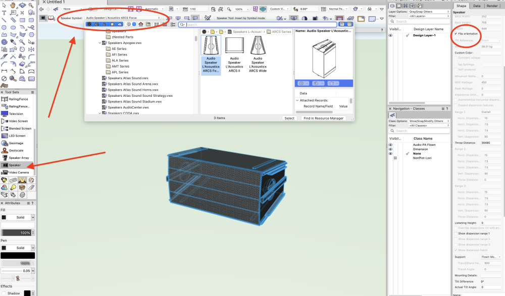
Cheers,
Peter
-
Hello,
Not sure what is happening to the turquoise rounded rectangle as that has different selection handle colours than the other two. It looks locked, but it all works ok for me.
Either way you are right in that for now I also can't find anything in the excellent Help about differences between the main menu Align/Distribute command versus the contextual menu Align/Distribute options. I will ask about this.
There are two main differences. Loci are treated as normal objects, and whatever is right clicked on becomes the object for the operation.
Cheers,
Peter
-
1
-
-
Even if I have Shaded settings set to Low the same thing?!
-
M1 64GB UM MBP macOS 13.3.1 No external screen.
?!
-
- Popular Post
- Popular Post
Wow, this is the first time I've been able to fake a mirror ball. An Array of Renderworks Spotlights at 90º with a dot gobo texture in all 6 of them, coupled with a sphere with a mirror surface as a symbol spinning! All due to SP3 amazingly allowing any texture be applied to a Renderworks Spotlight plus then Michael's spinning script!
Plus it's going in the opposite direction of the revolve! I'd still like the following:
- Being able to bring it back somehow to it's original start position otherwise it's trial and error and hitting the space bar to stop
- It would be great to choose the degrees up to 360º. Maybe if 360º is chosen it just keeps spinning and that is the default?
- Somehow be able to couple it up with the animation export so users can control the number of frames and size?
Either way in a seemingly short period of time Michael you've created a really easy to use and very useful script that answers @DiggleDesigns original question so much better than my feeble attempt!
Cheers,
Peter
-
5
-
That's brilliant Michael and so easy thanks!
Is there anyway to specify the degrees eg 180º or 360º etc, and/or specify the number of revolutions?. It seemed to finish with my file with the revolve facing upstage. Is there a way to reset it to the start position?
Also, odd things are happening in the Shaded render in my file with the walls 'flashing' and disappearing. Is there anyway for the render to hold? It's not the lights or Renderworks background.
Cheers,
Peter
-
1
-
-
Here's a Orbit with the same file. Much easier to edit because it's not on a slant like the Spin path. I'm thoroughly confused because maybe the orbit is the way to go?
The only difference I can see is that the spin path is angled. Vectorworks file enc.
Cheers,
Peter
-
1
-
-
The camera moves around the model but it gives the effect of the model being static. Please see the enclosed file with a more simple set to reduce file size. The hardest thing once the user has mastered getting the animation path level and shortened, is to set the camera view for each frame to be the same location in the centre of the page. So in my quick example above the camera wobbles.
Cheers,
Peter
PS Also if you don't already know from I think SP3, Renderworks Spotlight lights can have any texture applied and thus projected. Try projecting bricks - it works!


How to create a curved bench seat with vertical batten array back rest
in General Discussion
Posted
Well done. You might also want to change the View>Rendering>Shaded Options>Quality to Medium or High for when you output.
Cheers,
Peter