Thomas_
-
Posts
47 -
Joined
-
Last visited
Content Type
Profiles
Forums
Events
Articles
Marionette
Store
Everything posted by Thomas_
-
Assuming I understood your differentiation from correctly, a term panel would be primarily passthrough connectors correct? This isn't the case for a panel I design necessarily, I might have soldered connections just the same there as well. Though I will admit to possibly being still confused on that differentiation, I don't find it very clear in the documentation I have seen on it. EDIT: And there have been and will be cases where I want both on the same panel as well honestly. Though truth be told I am not sure why there needs to be two different tools anyways for this honestly. It feels like the differences (Soldered vs passthrough) should be options on the connector symbols that are easily switched between, and that a single panel type could cover both. I might be able to make this argument for a jackfield as well, though that is easier for me to agree on a different panel due to it affecting connections between sockets (normal, half-normal, etc.) Thomas
-
Thank you! Thomas
-
Ahh that might be why I didn't find it the first time, good to know! Thank you. This does bring up another question, is there a way to show the quantity of summarized items? For instance in a recent system I had 8 mini-converters that summarizing would shrink them down to a single row, which is great, but I would love to be able to get the quantity at that point to still know how many are needed? Thanks! Thomas
-
Ahh that might be why I didn't find it the first time, good to know! Thank you.
-
Thank you both, I swear I looked there, but went back and double checked that and realized what I was looking for (Equipment.User1) was under Field Value, instead of Record, sorry about the noise. Thomas
-
Hmm not sure if I am misunderstanding you here, or you me. What I am really looking for is an easy way to have a single physical device in multiple places on a schematic to help clean the schematic up. In doing so, removing ports that are in use elsewhere seems like a good idea. So my ideal is actually be more along the lines of: A command to take a schematic block, and make it two 'linked' blocks. If a connection is made at one of the two linked blocks, that port is 'disabled/hidden/whatever' on the second block to prevent a second connection being made to the same port, at least on inputs (Splitting cabling on outputs is obviously more normal, and probably easily argued should be allowed though when talking about the possibility of splitting by connecting the outputs across both blocks it is less obvious and could be argued). Also in the same line of thought, when the drawing is checked, the 'Check Drawing' command as a precursor to actually checking things, might take the two linked blocks and treat them as a single device in terms of ports, to prevent labeling things as duplicated ports that really aren't. To tag along with this, a visual indication of the 'linked' blocks could be provided, and at least one standard I know of for this is explained in the USITT sound graphics guidelines document from 2008: https://www.usitt.org/sites/default/files/2020-01/Sound_Guildelines_2008.pdf See page 2 where you have two examples of ways a block drawing could be visually modified to show that it is 'linked' to another block elsewhere in the drawing, complete with an optional text descriptor of this as well. This is a tricky subject honestly I agree, and one I haven't given to much thought to, but one possible option would be utilizing classing and telling the Check Drawing command to ignore certain classes. This could even be defined by regular expression for instance, so that *IGNORE classes are ignored as an example only. So moving something into an ignored class would tell Check Drawing to ignore that class, and could be broken down by Equipment, Ports/Sockets, Connections, etc. each with their own ignore rules. But again I REALLY have not given that enough thought as it is really secondary to me to the above, but still a possibility to increase the power available to it. Thomas
-
Yes sadly not checking sockets/devices would mean losing the functionality for that brought by that tool, one of the strong suits of ConnectCad honestly. Would be nice down the road to get a little more flexibility out of it then, as it is a great tool, but use cases like the ones I brought up here do tend to break it. Thomas
-
So sadly not a clean solution then. Is there any way to tell Check Drawing to ignore certain 'errors' like this, or when I have an item with identical NAMEs to represent the exact same piece of equipment more than once on the schematic? Thomas
-
More of a generic question I suppose, but specifically in ConnectCAD is there a way to filter worksheets, such as when I add a user-data item for 'Owner Furnished' (OFE) or not and want to run a report for a BOM that includes only devices that are not owner furnished to hand off to the contractor? I can obviously export to Excel and filter there, but would be great to do this in Vectorworks as well not only to simplify workflow, but also to more easily include it on output PDFs. Thomas
-
It has been option previously, at least it has worked. Issue arises when you have example some small devices(3-6pc) from different manufacturers which you know that fit in same real life rack unit and are to be installed to generic rack shelf with out dedicated rack mount. There right most units might not get RackU location to schematics. Half rack might be option in this case. Some times it is not when you have to put two little ones on top of each other. Agreed, non-rackmount items are very common in tour racks, etc. for instance as much as I might like to have everything rackmount, not always a case. One example from a current project is a blu-ray player, where for my client I can either spend <$100 for a non-rackmount or +$1000 for a rackmount, guess which one they went with? This also applies for a lot of equipment that just isn't rackmount like small scarlett audio interfaces, etc. Thomas
-
Ok, I will try this moving forward then, but will I get issues with the 'Check Drawing' command though as the ports still exist at that point? Thomas
-
Thank you, the select item command was precisely what I was looking for. I knew you could edit in the worksheet, however I needed to know what the device was before I could edit it, which finding the device in the schematic was what gave me that information. Thomas
-
On a roll with questions I know... So in one of my systems, every time I go to ConnectCad>Layout>Update Rack Elevation I end up with an 'unnamed' device on the rack layout. I can confirm this device is present somewhere in the schematic as I can go to the schematic layer, ConnectCad>Documentation>Current Layer Device Report and see a row that is an unnamed device. How can I locate this device on the schematic however so that I can either delete it (If it isn't supposed to be there which I suspect) or correct it so that it is no longer unnamed and has the correct height/width/etc.? Thomas
-
Understood thank you, that may better explain the difference of a CTP and a TERM panel to me (Wasn't really clear from the description). So a Term panel then is a panel with pass-through connectors, or is that only a small part of it? And how would one built a panel with both pass through and otherwise? Where should I look for more information on creating custom sockets/devices for this? Is that going to be the same as a typical socket for equipment or otherwise? Thomas
-
Actually glancing into this further, I noticed the Label Style under advanced customization, could a custom label style be created and then these ports set to use that? If so where would I look for more information on creating such a style (Likely based off duplicating and modifying the original)? Thomas
-
So in my drawings to keep cables clearer, I often will end up with duplicated equipment, meaning multiple blocks on the schematic, with the same Name/ID and refer to a single piece of equipment, but appear multiple times as that is the clearest way to indicate it. In these cases, I don't always want every port seen on every copy fo the block, for instance if I have inputs 1-6 patched in one area on my schematic, in the second instance of the block I might want to hide Inputs 1-6 so that it is obvious those are not available. Right now there are two ways I could think of to do this: 1. Edit the symbol and delete those ports. Tested and known to work, but undesirable as it is not easy to undo if I change routing down the line, I have to recreate the port[s] from scratch rather than unhiding them 2. Class the port to a specific class I then make not visible. (Untested, not quite simple and I am guessing might break something with connectcad anyways). Is there any other way to handle this situation or is one of these the best option there is? In a different unrelated thread that needed something similar it was suggested to take text size to 0.1, which could be another possibility I suppose? Thomas
-
Agree with Arto. The problem with Text Above is when you have multiple panels on top of each other it gets confusing, and while it may make sense to in some cases make those a single panel, in one system I am working on right now I have to work with what is already there and my documentation needs to reflect it, so it isn't always a possibility for that reason, or because it wouldn't make sense to recreate, for instance, a Cat6 patch panel vs an off the shelf one, just because I need to add a few more XLR or whatever under it. Ill give the text size thing a shot though, that may help. It may also be the best answer to another question I have I am going to post about in a moment... Thomas
-
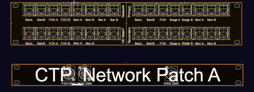
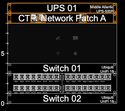
Is there a way to hide CTP panel names in the sheet layer? Or an alternative to have them display to the side of the object in the 2D rack view (And thus sheet layer) maybe? I ask as I am trying to, for instance, use a crop on a viewport in 2D rack elevations, to give a detail of some custom panels I need a contractor to make for the system, but the text of the title gets in the way of clearly reading the drawing. If I make the text above, it gets in the way of other panels. See screenshots for examples, the first is on a sheet layer, where I am trying to do detail viewports of the panels for the contractor to see, the second is on the design layer, where you can see if I made that network patch CTP label above, it would interfere with reading the equipment above it (The UPS). Thank you! Thomas Vecchione

-
So it does help, though doesn't address things like passthrough connectors that could be a part of a CTP, for instance RJ45/8P8C connectors like this can be common in network racks, where it takes an 8P8C plug on both sides to pass the socket through rather than having a punchdown on either side (Or term, or soldered connection, etc.) But it does explain the thinking a bit at least, and the expected workflow. It is a good thought, not sure I agree completely with it, but at least I understand it. Thomas
-
So no idea what changed, but it suddenly started working. I spent a good hour trying different combinations to get it to work, so something seems to have been preventing it from working, but not idea what. So if anyone has any ideas of a common mistake that would cause that I would love to hear it. Related to this though, there is no option to select an IO port for a CTP connector, but obviously some things like RJ45 really should be. I could probably argue most of them should be if not all by default, as they will be passing through data/signal. What is the thinking on this? Thomas
-
Is there a way to connect two connector panels together? IE. I have a system I am working on currently, I have connector panels in the performing space, that will come back and connect to a connector panel in the rack in the AV closet. If I have equipment I can drop the connector panel connections on the connector lines, but in this case many of these are not intended to always have equipment connected. So I have an example below where I am trying to lay out the infrastructure for the building (Performing Arts Venue). I will have panels at FoH, Monitor World, either side of the Balcony, etc. At any given time one or two of these positions may be used. All of these connections are going back to the AV closet, where the Cat6 connections especially are going to a panel, which would then be patched directly into a switch. Right now if I try to draw a line between the CTP connectors, I get an error of no output socket found, even if the connector is an output (Which also begs the question of how IO connectors like RJ45s are handled?) Is this a matter of CTP not being correct and I should be using a term panel? My reading of the help was that was intended primarily for the rear of portable racks for instance. I tried Term panels as well without luck. In fact the only thing that seemed to allow for outgoing connections was a jackfield, which definitely isn't what I am doing here. Literally just want to document that two CTP panels connected to each other, number the wires used for this, and on the other side of the second of a pair, show the patch into the switch. No input into the first of these in most cases. Thanks Thomas Vecchione

-
For the record I agree with the OP in this thread, just had the exact same problem. In response to: How is that any different from the having the names get overwritten when you update from the schematic through 'Get Connectors'? The only real difference I see is that in that case you can see the changes happen and know you screwed up. But realistically then there should be an operation in the reverse, you should be able to pull in changes on the schematic to update the name if you are worried about making sure it is always visible when the change happens (Though how true that is can be debated in CAD in general honestly). I would argue the converse of your point -- if you see it, you should be able to edit it safely and have it flow through your drawing -- should be true and it often isn't in ConnectCAD. Part of the problem I am having with ConnectCad in particular (And Vectorworks in general to an extent though not as much as it used to be going off memory) is that 'There is only one workflow' instead of 'Hey this is one possible workflow' or even 'This is a suggested workflow'. It makes it very difficult to wrap your head around, for instance, making connector panels when it seems like you should be able to do this X number of ways, but every way except Z breaks things unexpectedly. For instance the first time I tried to make connector panels, I tried to create them without making it on the schematic first. Failed miserably obviously, despite it seeming like that should be possible. Thomas