


DDD
-
Posts
111 -
Joined
-
Last visited
Content Type
Profiles
Forums
Events
Articles
Marionette
Store
Posts posted by DDD
-
-
HI all,
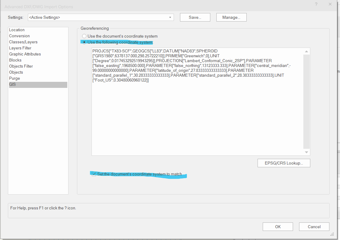
I have a question regarding handling cad file with geolocation information. I do the following procedures:
a. when I see the "georeferenced file" is auto checked, I go to the advanced setting:
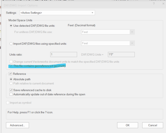
b. I make sure the highlighted items are checked, then start referencing the dwg.

c. after importing/referencing, I turn on the geoimage and it looks good. The referenced drawing is on the corrected spot with correct user coordinates.
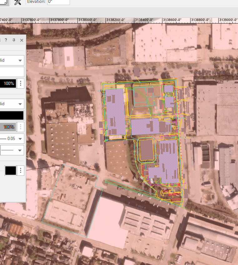
d. However the drawing ends up being far away from the internal origin
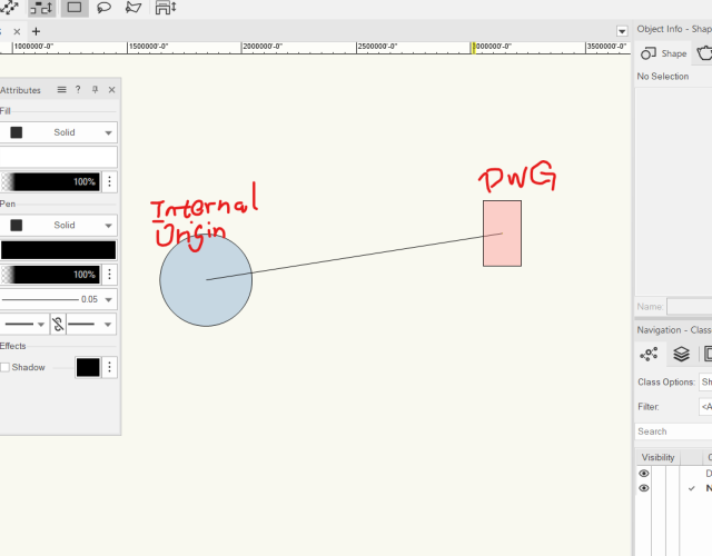
Should I proceed with this or do something to fix the problem? I tried "center drawing on internal origin", but this will mess up the geolocation. Thanks in advance for your help!
-
On 11/17/2023 at 3:35 PM, Your Name Here said:
You can use 2D illustration tools like polygons in plan and elevation views. They will show in 3D views too like billboards seen in other software like Revit.
But that's not an image prop, it's a vector representation.
Could you please elaborate the 2D illustrator? Are you referring to drawing 2 different polygons to represent plan & elevation?
-
Hi forum,
Is there a way to make polygon based - image prop for plant objects? I know there is a way to generate from image. I am looking for polygon based approach so I can have more control of line and fill color. Something like what Revit is having now. Thanks!
-
@jeff prince You are the legend, I never thought about this solution. Thank you so much!
-
 1
1
-
-
Hi, I am having questions about site modeling, please see attached file (2023 Landmark)
-my goal is to model as below:
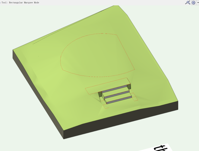
-I modeled the retaining walls and pads on one side, it goes well.
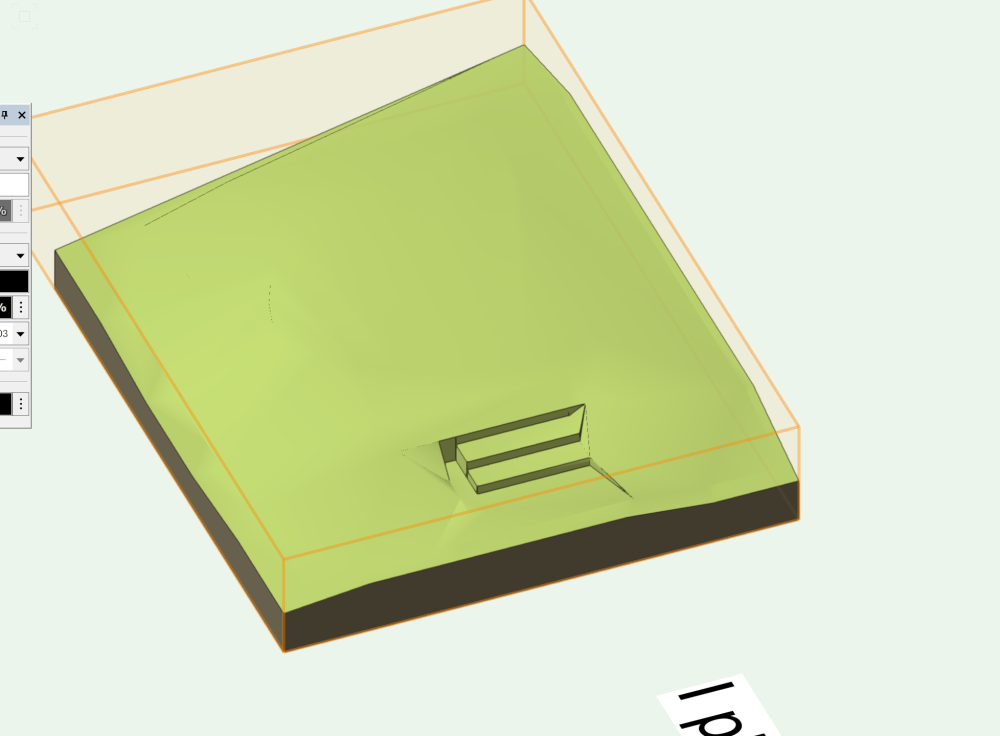
-But when I mirror the pads to the other side, the model is messed up, any thing I did wrong?
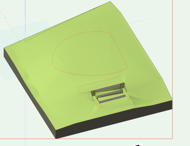
Thanks in advance!
-
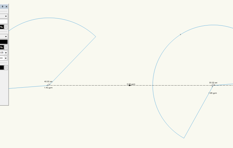
20 hours ago, jeff prince said:
Replying from the field, so I can’t open your file. Did you connect your pipe to a mainline, valve, and POC?
Hi Jeff,
Thank you for the reply. I figured it out. Looks if I just connect two outlets it won't return any pipe flow. I will need to extend the pipe out for it to calculate.
-
Hi all,
I am super new to the irrigation design and I started off with tutorials in the VW University.
https://university.vectorworks.net/mod/scorm/player.php?scoid=32&cm=98¤torg=articulate_rise
In the "placing pipe" section the video is showing new pipe drawn and connected to irrigation heads will generate flow number automatically. however, this is not the case for me, new pipes I draw are showing 0 flow number and I don't know how to fix this. Anything I could be wrong doing here?
Thank you in advance,
-
44 minutes ago, Pat Stanford said:
I have not been able to make it work in a Spreadsheet Cell, but I can get you the data in a Database.
Make a database that lists all of the plants (or a subset using criteria).
Set a column to display your tag and SUMmarize that column.
Set a column to ='Plant Record'.'Quantity' and check the Sum Values button.
If you add another column with a formula of =Count, you will get a count of how many individual plants and how many groups have each tag. For single plants the Count and the record.Quantity should be the same.
My version of the file attached.
planting count v2022 Pat Version.vwx 252.01 kB · 0 downloads
Thank you, Pat!
-
5 hours ago, Carol Reznor said:
Hi
Maybe instead of using the tag as a criterium you could use the following in your worksheet
the Insertion options Mode (Formula for worksheet header: ='Plant'.'config')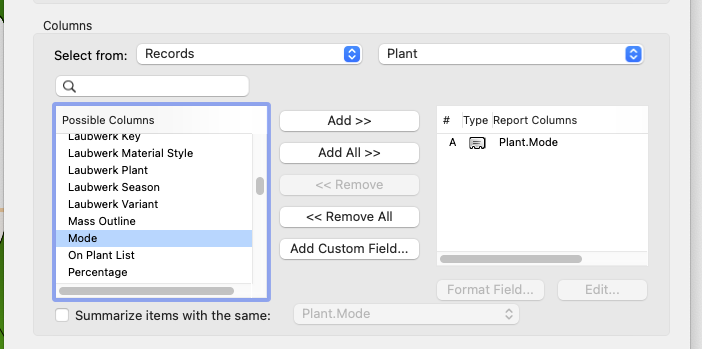
This will allow you to list or filter by how the plants were inserted as a single plant or as a group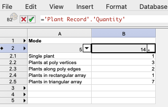
CarolThank you!
-
On 6/21/2023 at 12:57 PM, Pat Stanford said:
Can you show us the Auto Text setup for the text block that shows the count in the data tag?
Hi Pat,
Sorry for the late response. Yes please see below
#Plant Record#.#Quantity#
-
8 hours ago, Katarina Ollikainen said:
Hi, if you report on plants (Plant Record) instead of the count of data tags, you'll get the correct quantity. I've added a very simple database report to your file, but you can use one of the preformatted ones - they're setup the same way.
Hi Katarina,
Thank you for your response. My problem is that I need to not only report the total planting quantity, but also be able to report planting quantity under different tags in the worksheet. In my case the expected result would be "single tree -3" & "grouped tree - 3". Another similar practical scenario is that I am creating a shrub group and tagging it as "group A", in the worksheet I am only able to report number of "group A" shrub as 1 instead of the actual quantity.
-
Hi all,
I am working with worksheet report and I have a question for worksheet report.
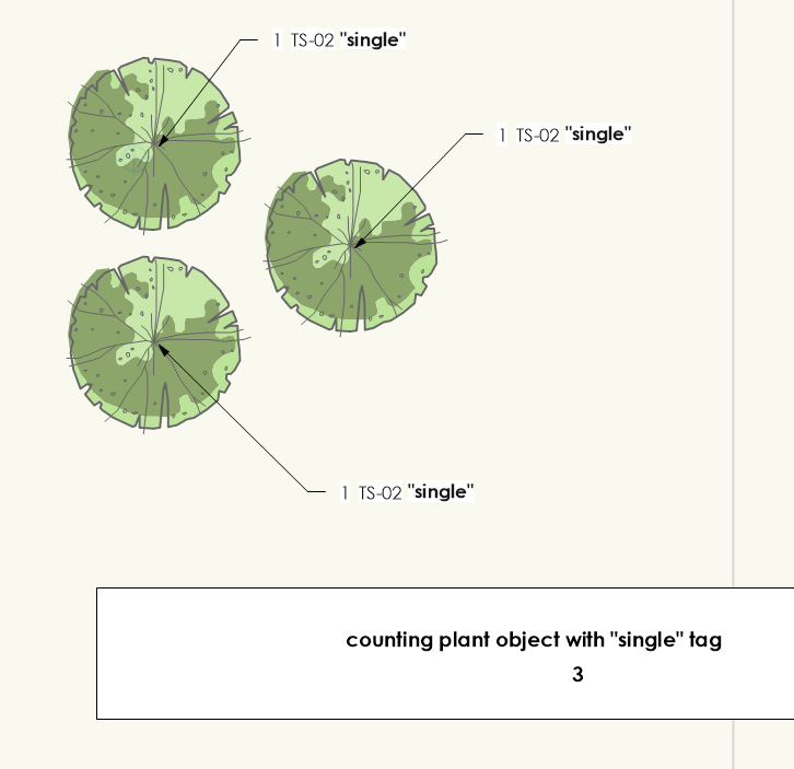
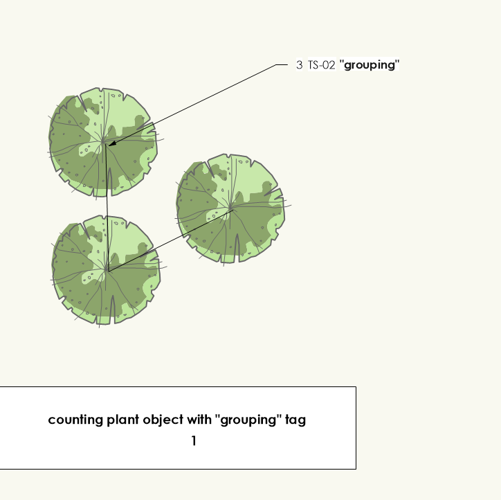
I have two sets of plant objects with different tags, one group is tagged "single", and each planting object stands alone. The other is tagged "grouping", and all plantings are grouped. My goal is to report plant quantity of different tags in the worksheet. The formula I am using is
=COUNT((('Plant'.'TagSchemaCenter'='"single"')))
&
=COUNT((('Plant'.'TagSchemaCenter'='"grouping"')))
However, the grouped plant objects can't return the actual quantity, it is reporting 1 as opposed of 3. Is there anyway to report the actual plant quantity instead of plant object quantity? My file is attached and thank you for the help.
-
27 minutes ago, Kevin K said:
Do be mindful to check your shaded options...
I will bet money that if you check that, your setting may be set to 'low'. Make sure it is set to at minimum ' high'
Yes it was set to high all the time, maybe it's a 2023 thing? I notice you are working with 2022.
-
16 minutes ago, Kevin K said:
@DDD Good you had some success sorting out the issue(s)
One thing to be aware of..almost all of the native VW plant image props come in with the reflecting channel set to 'Glow" or as they call it 'constant reflectivity'
I have found when rendering a scene with the reflection option to use the 'glow' setting, the image prop is a bit too intense.
So....I usually set that to 'none'.
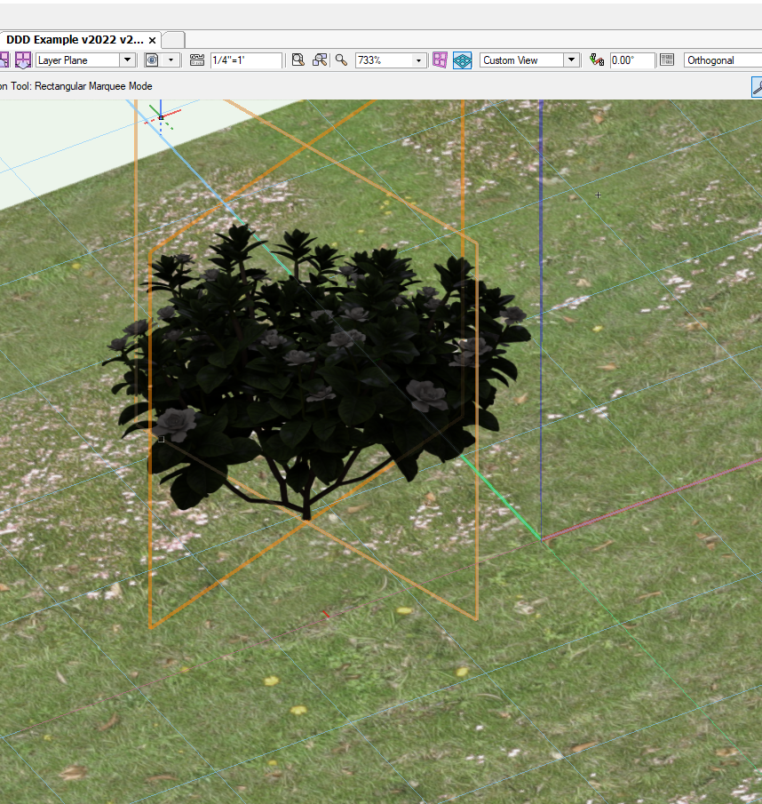
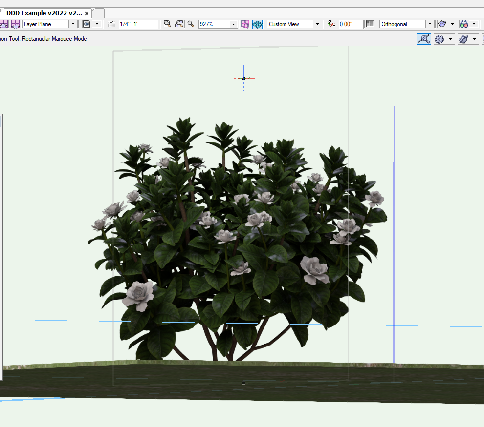
As far as the your comment about it appearing 'dark', are you referring to YOUR image you sent me? Or the gardenia I included??

The darkening happens to all image props (yours & mine), I attached the images. I turned on the "glow "option in texture setting and it turns out great. Glad to know this trick! Currently I only present plants in shaded mode so I guess I'll turn the glow option on for better visibility. Thank you very much!
-
14 hours ago, jeff prince said:
it sounds like you have your image editor set to the wrong color profile or the image you downloaded was saved with the incorrect one. Verify it is set to sRGB before importing into Vectorworks and you should be good. This happens with aerial photos and other image based resources too, so something to be aware of.Hi Jeff,
Yes, in Photoshop I exported images with the white 'background' layer on, and looks like that is causing this issue.
-
 1
1
-
-
14 hours ago, Kevin K said:
@DDD Ok, sorry for the delay. Had to attend to some life things 🙂
Without having your actual file, I can't really discern exactly what's happening to make the image sort of a grayscale with no color.
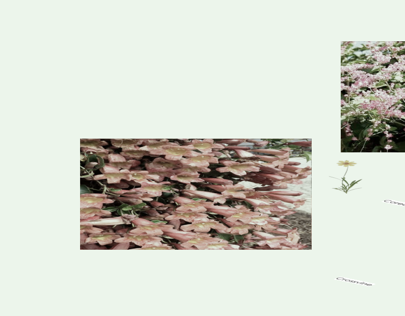
That said...here is the deal....when you upload images (plants especially) to use as image props, you need to normally have some space around the plant parts.
Case in point:
Your image:

An image example of a gardenia that I included in the attached file:
Note all the black area around the actual plant. So that part will be used as an image mask so when you create the image prop, that part becomes invisible.


Feel free to import the plant/image prop in the attached file, into YOUR file. It should appear without all the faded coloring....but it will appear but because of the base image it won't look that great. Compare it to the gardenia 🙂
Hope this helps.

gardenia.psd 962.23 kB · 0 downloads gardenia 2.psd 3.44 MB · 0 downloads
Hi Kevin,
Thanks a bunch! I did some more tests and I kinda know how to get it right. Another question is the image prop looks dark when viewing from a higher point. The color recovers back when the camera drops down to level elevation. Is this just how thing is?
-
4 minutes ago, Kevin K said:
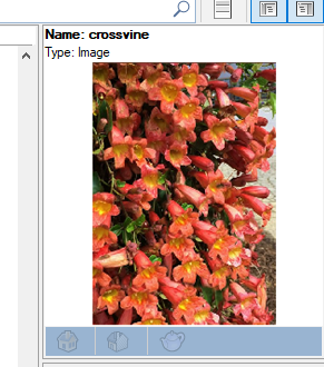
DDD not sure if that plant image is from the VW library, but if you wish, upload the image and I can have a look. It could be one of several things occurring as to why it is faded. Hard to tell unless we can see the image.
Hi Kevin,
Sure, here is the image. I just downloaded it form the web and re-export it as PNG in Photoshop.

-
Hi all,
I am creating new image props for plants, for some reason the outcome is desaturated. is there a way to fix it?
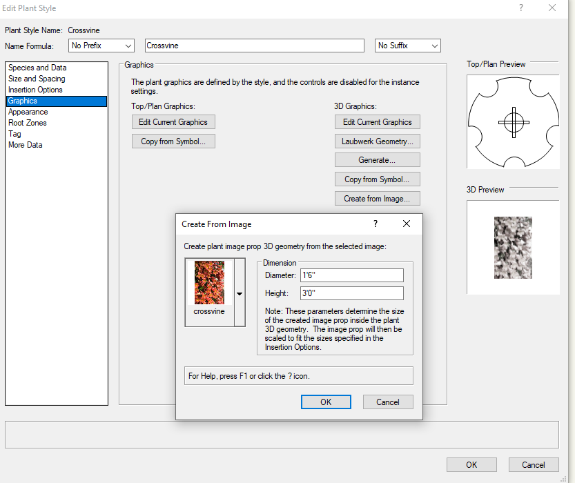
-
8 minutes ago, Tom W. said:
Cool. I misunderstood what you meant by elevation in your orig post. But I think #IPZL# returns the height of the bottom of the Wall relative to the layer it's on so if you're looking to show the elevation of the top of the wall above sea level the layer elevation for the Wall layer will need to be 0...?
Yes I am working on exterior retaining walls on a site model. I am labeling walls using their top offset elevation so this works just fine for me.
-
21 hours ago, Tom W. said:
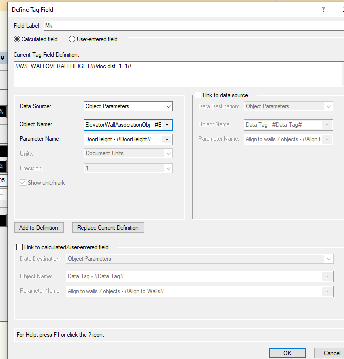
Try the Object Function #WALLOVRLHGHT#
Hi Tom,
thank you! This can work, though #WALLOVRLHGHT# is showing the wall height instead, I found another data tag #IPZL# can show the site model elevation. Sum those values will get me what I want.
Thank you.
-
1
-
-
Hi all,
Is there a way to create a data tag that will recognize wall objects and show their elevation info in plan view? I try to work it off from prebuilt wall tags but I can't find proper data link in it.
-
Hi all,
I am having issues with shadow catcher texture. I am trying to change all class textures override to "shadow catcher" in the viewport to render a shadow map. It is suppose to render only shadow in the picture, however, some objects are still showing. What's even more bizarre is that duplicates of same objects are behaving differently in the same viewport. Please see my file attached (2023 landmark).
Objects on left column are displaying incorrectly. Both objects and shadows are rendered.
Objects on right column are displaying correctly, only shadows are rendered.
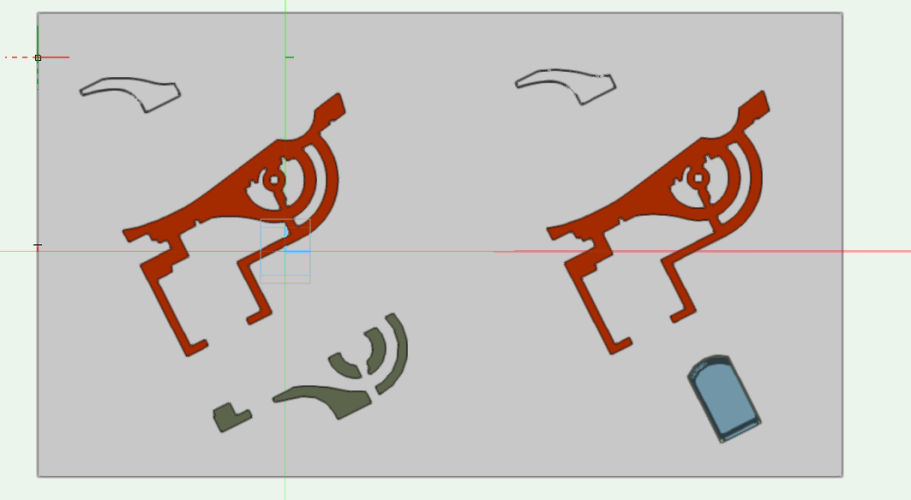
Is this a bug or something I did wrong?
Thank you!
-
Hi Jeff, thank you for the help!
-
1
-
-
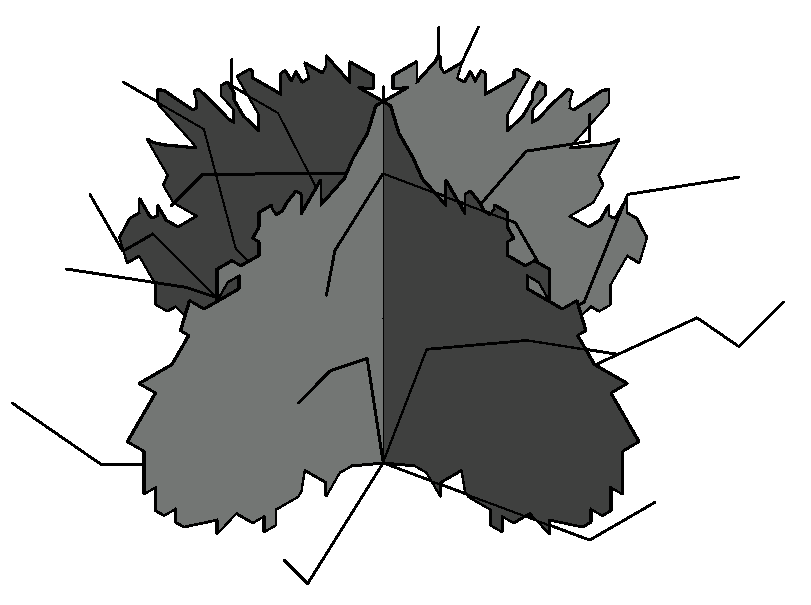
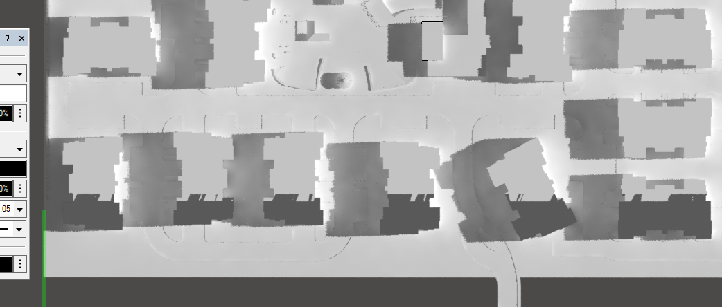
Hi everyone, this is another shot with white model render setting. Again the perspective view will display correctly, but the plan view shows something is wrong with the mass building model.

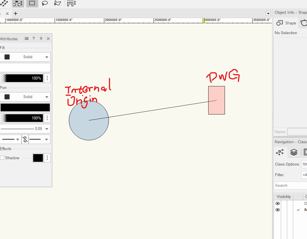


Having problems with geolocated DWGs Again...
in Site Design
Posted · Edited by DDD
Hi all,
After I posted the geolocated dwg issue, I came across with another weird behavior, not sure if it's a bug.
So if I follow the procedures I quoted above to IMPORT the geolocated cad file, it will be on the right geo-spot with right coordinates (note the coordinates on top and side ruler, not the geo stake)
But if I REFERENCE the geolocated cad file (with exactly the same procedure), it will be on the right geo-spot with incorrect coordinates (note the coordinates on top and side ruler, not the geo stake)
Any ideas? This is so buzzard...