


RichPiano
-
Posts
35 -
Joined
-
Last visited
Content Type
Profiles
Forums
Events
Articles
Marionette
Store
Posts posted by RichPiano
-
-
I didn't know that you could do such a thing, thanks. However, it didn't solve my problem. Classes can't be arranged in such a way right? I even changed object order but it still does nothing..
-
Hi guys
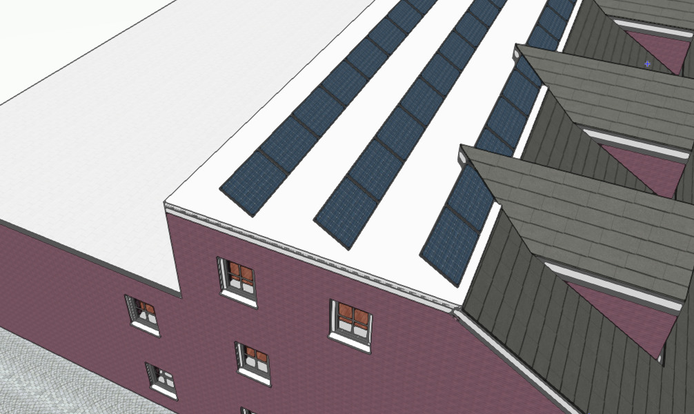
So apparently my object order got messed up when I inserted a new planar polygon on top of my building to put some green roof texture in. I inserted it below the solarpanels of course, yet in the sheet layer the polygon is drawn on top of them (it has 60% opacity). How do I change this / why does this happen?
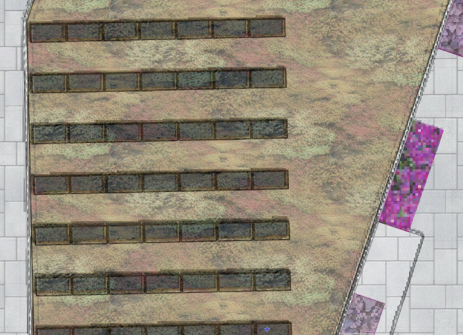
* to be specific: I would very much like the order to be like it is when viewed from the top...
-
Yes, the corresponding layers and classes are set to be visible in both, 3d view AND viewport. I think i will just extract a surface from the pavement and put it on top... I'm kinda disillusioned with elegant solutions anyway..
-
1. it's a way/pavement... idk what the correct translation in english is but it's that in german.
2. layer and classes of the object are set to visible
-
21 minutes ago, drelARCH said:
set viewport to 'Top' view
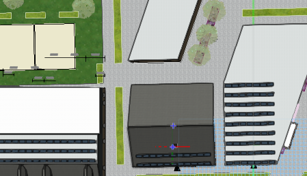
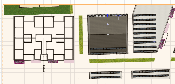
Ok "top view" works in the 3d view. But when I set the sheet layer viewport to "top view" it still doesn't show. Compare the screenshot on the left (3D view) to the one on the right (Sheet layer view). Why?
-
5 minutes ago, drelARCH said:
Hi @RichPiano
Change view to ‘Top’ will display texture.
Regarding slab: in Render tab of OIP under Mode you can choose from by object or by component. Try these settings.
Thanks! But what if I want to show the texture in my sheet layer?
-
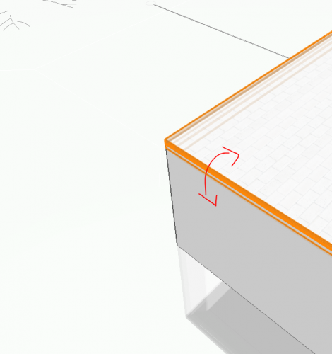
*still relevant
What is also very curious is the pavement surface which only shows texture in 3d view put not in top/plan view. How can I make it show texture in top/plan view also?
-
Still relevant. Does anybody know the solution to one of these?
-
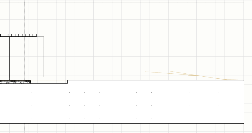
Hi guys
I want to change the appearance of my slabs, but I can't make it work somehow.
This is what I have tried:
1. Set rendering options to "shells".
2. Then chose "object class" for each wall shell.
3. Define the class in the class settings and change shell/object material to the one i wish.
But it just doesn't work, the slab stays white (see picture). What am I missing?

-
Thanks a lot guys!
I considered the options. I will probably just draw a line from the left- to the rightmost solarpanel, then drag the midpoint of this line together with the panels and align it with the midpoint of the walls. It bothers me however that a object axis are not a part of vectorworks. I used it a lot in SketchUp.
-
Hi guys
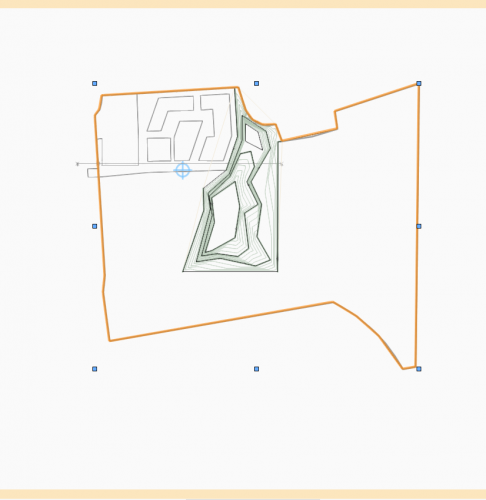
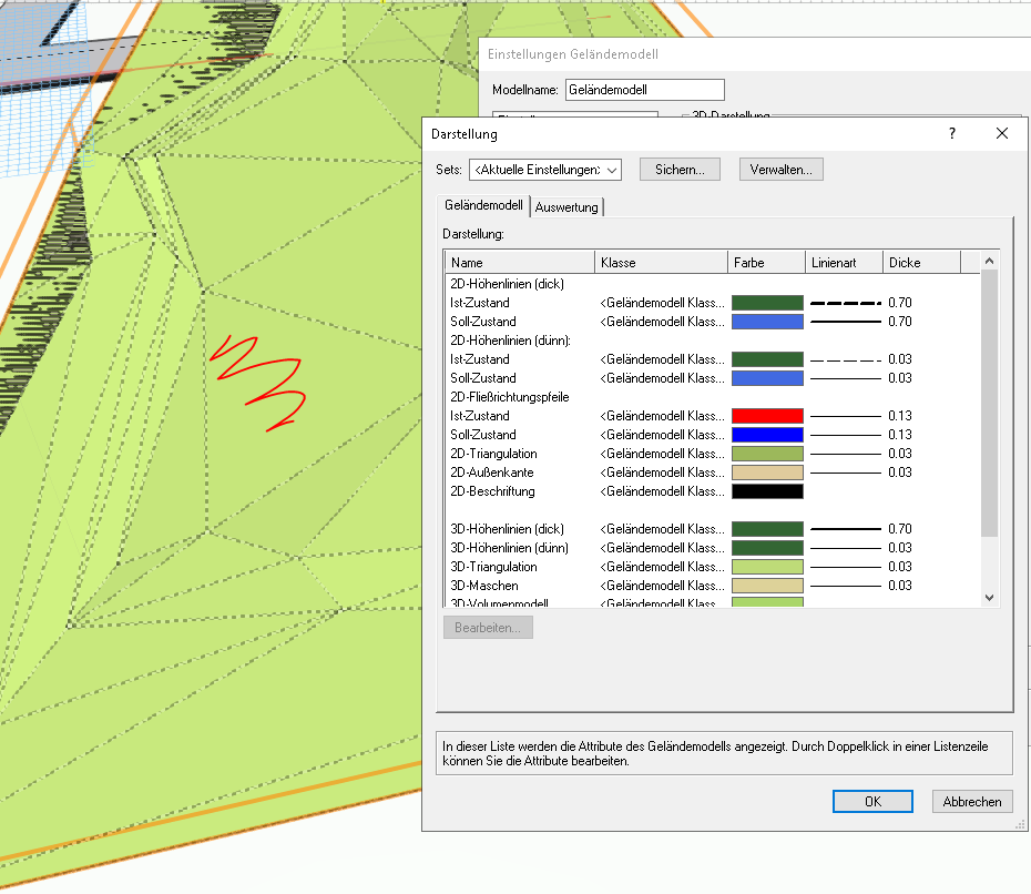
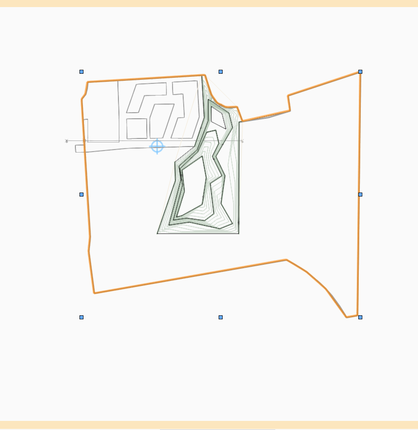
Three questions to landscape modeling:
1) can I add textures to the landscape model?
2) how can i add new height lines to the existing model? if I just create an additional 3D-Polygon it doesn't integrate it into the model.
3) How do i make cut sections through landscape models visible? It's just a scribble of lines as of now.

-
Thanks, but then the other bounding boxes in the scene won't fit again. Everything is at a different angle unfortunately.
-
Hi guys
I have an area of solar panels on my roof, that i want to align with the walls of the building. I grouped them together and now I want to align them to the left and right walls. However, to do so the border box around my group must first be oriented in the correct way. As you can see, it is off angled by a margin. Can I somehow define a local coordinate system so that the box fits neatly around the panels, maybe by rotating the local axis a bit?
-
@Katarina OllikainenThanks a lot that did work! 😄
-
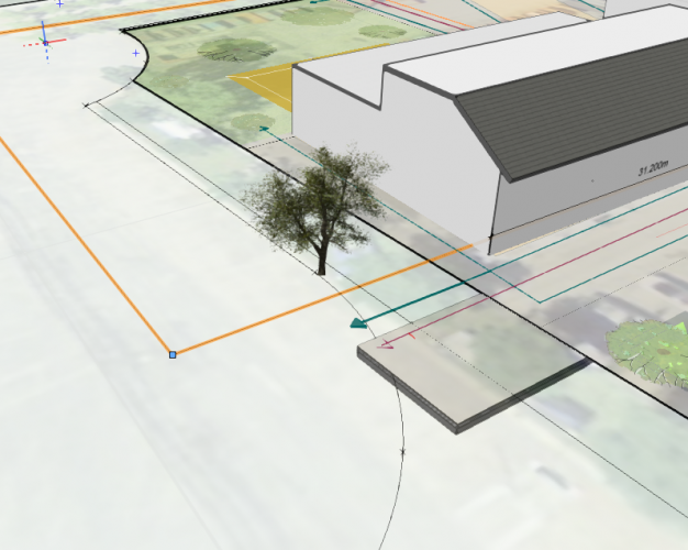
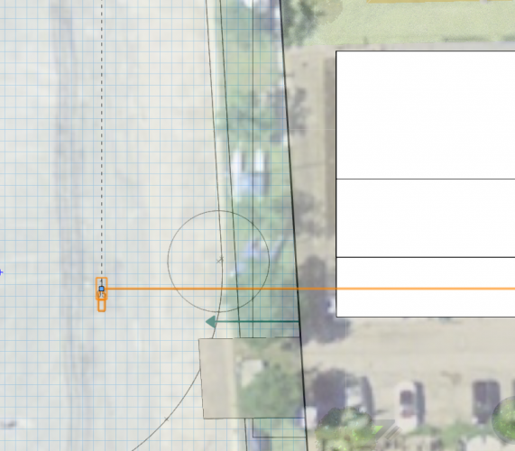
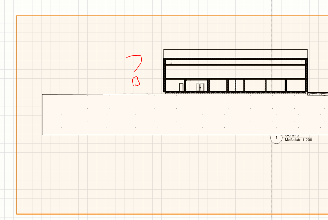
Hi guys
I have the following arrangement (see screenshot): A tree is placed behind a cut section. But it doesn't appear on the sheet layer at all. What am I doing wrong?
3D View of the situation:
Top view of the situation. Selected is my cut section:
Section viewport. Where is that tree?

-
Thanks! Now i know what design layer viewports are for! I will try it out soon!
-
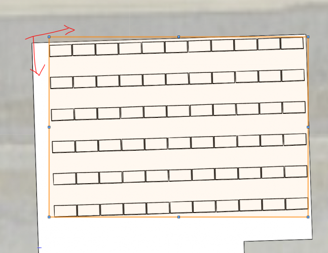
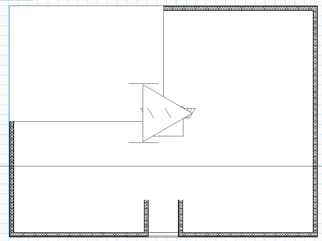
Hi guys
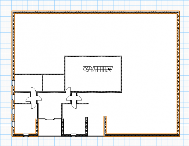
In the below floor plan, I want to mirror it so that each edge has the same division of walls. How would you go about?
Also: Is it possible to mirror it in a way so that the changes are automatically adapted to the other sections if i do them in one section?
-
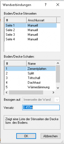
Hi guys
My slab somehow got disconnected from the surrounding walls. How can i reconnect it? Options are set to manual and the connection setup is greyed out.
-
Thank you, now i found it! I didn't think it would be this much work honestly haha. I also changed the scale of the design layers, that helped with other arrows that were way too big 🙂
-
 1
1
-
-
Thanks leecalisti! I have now chosen class attributes for the stair. Now I can change the color and line thickness, however i can't see where I would change the size?
-
Hi guys
I inserted a stair and now I can't see it because the arrow that comes with it is way too huge! How do i scale it down?

-
Ah thanks I get it! You have to choose the scale and then cut the borders after that 🙂 that's the workflow!
-
Thanks but this only increases the viewport size on the sheet layer. However, I want the borders of the viewport to stay the same but the object within should be bigger or closer.
Another way to explain it is: When i created that viewport, I used a rectangle and then Create Viewport. Is there a way to adjust that rectangle so a different portion of the object is being displayed by the viewport?
-
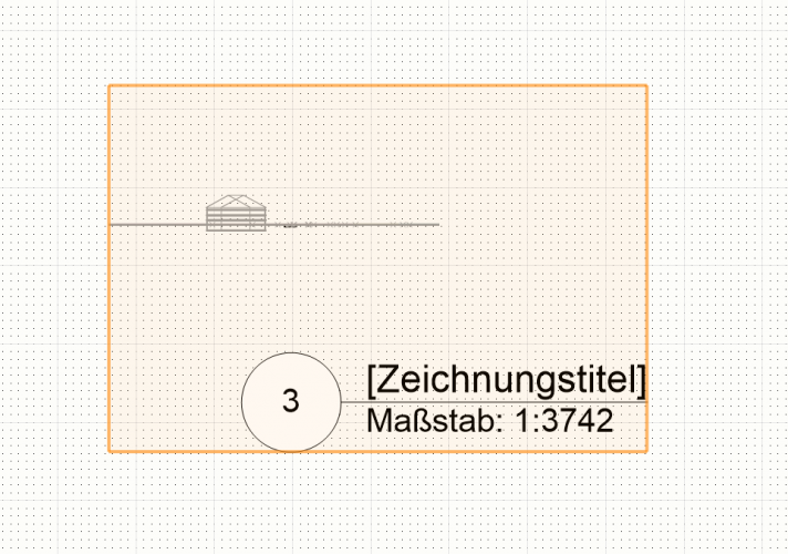
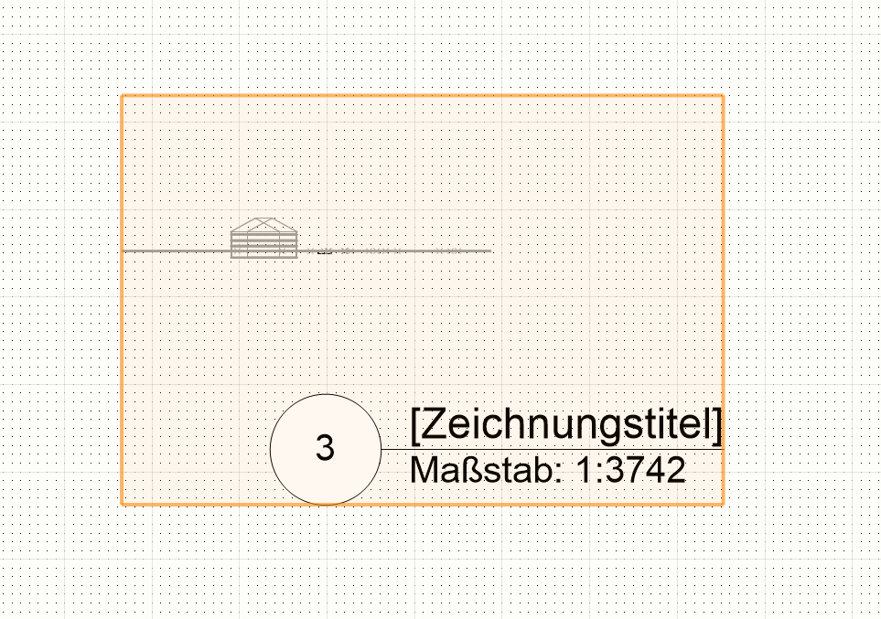
Hi guys
Have a look at the attachment. My house there is pretty small on that sheet layer... Can i scale it up so it fills the viewport?


Sheet layer object order
in Troubleshooting
Posted
Thank you I'm aware of those settings. But they don't change a thing. The order is still messed up 😞