KingChaos
-
Posts
261 -
Joined
-
Last visited
Content Type
Profiles
Forums
Events
Articles
Marionette
Store
Everything posted by KingChaos
-
Hi there, I am verY New in vw and i am struggling with the Missing parametric Design while modelling some cabinets ans similar objects. In the past i used Solid works, Solid Edge and topsolid. Is IT possible, to add marionettes in the History of the modelling Makros from VW? Fe i make a Volume Subtraktion and Then i enter the Subtraktion and place a Marionette for moving the subtractor or the subtracted Volume somehow? BR kc
-
How i can let me Show the Python Code or vectorscript Code of the normal Program Makros? Is IT possible, to get the Codes of the predefined Makros f.e. Draw circle, Extrude, pathed Extrusion, or the interiorcad Makros 3d-piece? In freecad the Programm will Show the Makros in a seperate Windows If in want IT. BR kc
-
IFC Data missing, after applying optical properties with pipette
KingChaos posted a question in Troubleshooting
Hi there, i got some IFC data vom Yacht intrerior designer here, and i am struggling with some Problems. 1. All the objects got ifc data, but the export-interface out of SolidWorks put them onto the ifc-container, which includes the Group, the Symbol, the Group and the geometry. clear is, that if i break the upper Level (ifc object) Group it will remove all the ifc data. 2. the geometrical objects are hided in some group-structure with up to 4 Levels. So if i enter the upper Level of the containers (ifc object) and break the inner structure of the Groups down to the geometry, it is more easier for u to use this data. 3. If i finished one object, i colored it green to ensure, that i dont Forget some piuce. After the 2. piece i finished, i pipetted the optical Information (green fill color) onto the 2. one. with the following adjustments. The 2. one went green, but all ifc data of the 2. objects are now blown away? This is not good. What i am doing wrong, or is this a bug or software mistake? 4. Is it possible, to add the ifc data onto the last Level, where my geometry is, or how my solidworker has to Export the geometry that there are no containers and i only get the geometry with my ifc data? 5. The yachtdesigner uses solid works but his exportdialogue and his Exports has no structure what i Need in vectorworks. Is there some procedure, that he can Export it with real geometry without inner structure. Maybe some guys here have experience with importing ifc- data and so on. br KC
-
add a rotation parameter to an existing Objects with marionette?
KingChaos replied to KingChaos's topic in General Discussion
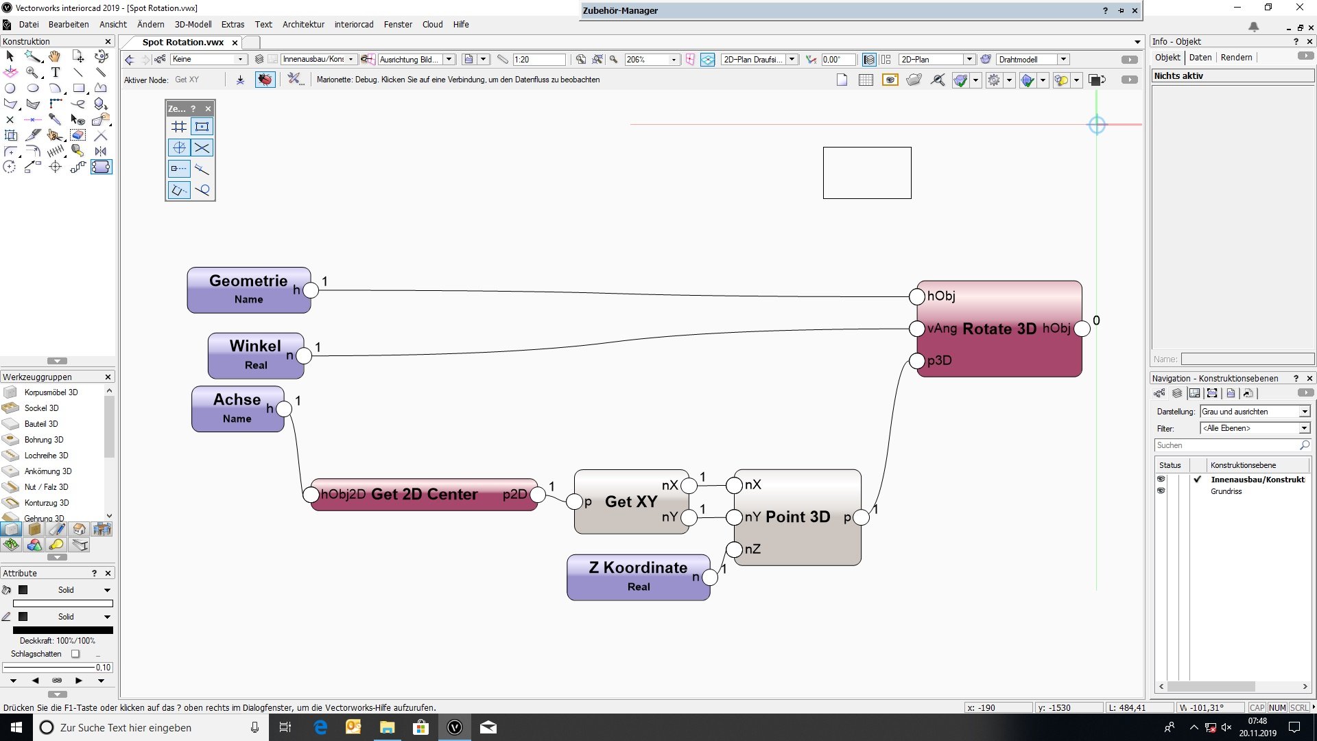
thats how me as a marionette newbie thinks i might work somehow, but how to continue?
-
Good morning, after a while practicing VW i now think there might be some way for me to "resurrect" dead geometry with the marionette tool. I got a spot geometry and i want to make it rotate/inclinate the spot and maybe dim its lightsource with a marionette code, if this is possible too. MAybe u can verify or falsify my thoughts here. Is the "create custom object node" the right thing i need here? IF so, i need a little help to use the marionette script to do it. How the placement of the predesigned geometry will work. But so far i dont know how to use the marionette to place a predesigned spot geometry and how does it work for me to put it into a vwx file. how IS it possible, to rotate the spot (inclination) around a predefined axis? I think i need a simple line in the axis where i want to incline it with a name to define the rotation axis for a rotation node. Then i will make a inputnode for the angle of the inclination and a float input for the percentage of the lightsource (dimming). WIll this work somehow? IF i succeed with this, i can really make parametric objects out of dead geometry. How to wrap it so, that i can use the parameters of the marionette to manipulate the spot? BR KC
-
Hello Pat, thanks for the answer. i think i can reduce the params down to 30 different. Which node oder python/vs i have to use for changing the symbols/pios? But my problem is, that i f.e. dont know, how to place parameter measurements in the drawing. In TopSolid all you do is get a param for each distance u draw and that makes it very strong. I pyramided up to 10 levels or files with putting all the params down to -9 lvl. I saw a vw video on youtube, where someone disactivated "show value" of a measurement then uses the prefix (parameter name) and suffic (formula). With a polyline (rectangle converted into poly) he made around all the stuff he wants to change and then he grouped the measurements and the polyline and they worked. But it was only in 2D. Maybe someone can help me find the clue in using parametric measurements for 3d-parts in the interior module. I made a 3d part (19 mm plate) then another on on the topsurface of the first, placed a measurement and modified it. i found to different results, 1. my first plate went from rect to trapezoid and 2. the measurement shrinked and lost connection. and how does the stuff with the intelligent objects work? i need more videos, where someone made anything. The new job, where i need this, will start on nov, and i am quite forward the scedule with my learning vw. The first vw seminar i will get in November. The more stuff i know til then, the better questions i can ask the seminar teacher. Maybe you have a link for a video, where someone makes a pio which is placed like a wall. The insertion mode is prob. "click-release mouse"? br kc
-
Hi there, i am despairing on trying to place some 3d parts with parametric distance out of the interior cad menu. I made a aquare plate (with 3d part) and then on its surface another plate. Then i made a measure (its the way other programs do it) to define the position of the 2. part relative to the first ones geometry. As i changed the value of the measure, 2 possible things happen. 1. the measure gets smaller while loose their connection to the 2. plate 2. it morphed my 1. plate to a trapezoid? what i am doing wrong here? br kc
-
Hi Folks, for an interior producer i have to make such a parametric modul and it has to be place like i can do it with the wall . The Module includes app. 50-100 different subassemblies (Glas, LED, all the woodworking stuff particle boards, steel parts, fittings, refrigeration etc.). Is there a good video in the video library of vectorworks how to make those "intelligent objects" and how to use these plugins i found in the menu? I found the marionette tool, its very good and works well. Think i have to combine it with the plug in stuff. Today i defined such a plugin, made an icon 26*20 size , but all i can do is enter python code, if i interpreted the menues right. In which menu bar it will be appear? I cant "open" the plugin to place some elements, symbols or else. AND it must be possible to change parameters and so some subassemblies has to be replaced with others. This function i did not found yet, and i hope there is such a possibility. The logic of what parts, fittings etc is totally clear, the logic functions for this are in my head. But where to start and how? I made it once before with TopSolidWood (parasolid kernel + total associative Construction 3D-CAD made of the TopSolid_6 Metal Version) and it worked very well. i made complete counters (with app. 80 changeable parameters +50 fix parameters) of 15 m in app. 2 hours with all functions for production and rendering, part lists and drawings of the glass with all drillings etc. fully automatic. But now it has to be done with vector works. BR KC
-
how to make parametric buildings and rooms?
KingChaos replied to KingChaos's topic in General Discussion
thx -
good morning, i am new to vw and i am kind of spoiled from topsolids parametric and total associative construction what i did not found in vw. The problems i have, drawing wall or floors is that i dont know the exact geometry of rooms or buildings. I have to manage and create interior designs for shops but the measurement of the shops is in the offering phase not totally clear and exact and can only be taken from the rooms, when they are empty (only a few days before the fabrication of furniture). but the measurement for offering will be done in complete equipped old furniture. It is not exact and has to be adjustet. but how? if i modify a wall, the floor will not follow, and so on. 1 weeks before i have to send the construction drawings to the joinery we take the exact maesures of the then empty rooms. It is impossible to redraw, reconstruct or modifying all applied furnitures after i modified the walls f.e. How i can manipulate the outlines/contures of walls with simple parameters, so i can place all the cabinets, counters, shelfs before we got the exact measurements and then "only inscribe exact lengthparameters"? is there even a possibility to use parameters? i did not found anything. 😞 br KC
-
hi there, i am triying to reduce the complexety of a solid with faceted surface f.e. a downloaded banana of sketchup warehouse to use it as decoration of a green groocer shop. br kc