


Conrad Preen
-
Posts
1,094 -
Joined
-
Last visited
Content Type
Profiles
Forums
Events
Articles
Marionette
Store
Posts posted by Conrad Preen
-
-
No worries!
The way devices are implemented is by design. There is a whole host of reasons why you might want the same make/model to appear differently in different instances. You may want the sockets arranged differently so as to uncross circuits. You may want to show only the relevant sockets and not clutter up your drawing with unused stuff. You might have half the device on one layer and half on another (eg. audio and video drawings). ConnectCAD gives you a lot of flexibility like that.
Equally there are good reasons not to have a situation where you edit a device symbol (say you delete a socket) and suddenly on a layer far far away you have a disconnected circuit you had totally forgotten about. This is what I mean by unexpected consequences.
We are developing a tool that will let you copy content from one device to a selected group of devices. That way you will be able to preform mass edits but explicitly with nothing happening behind your back.
Conrad
-
Great questions!
21 hours ago, Cookie_NZ said:1. As stated in this post, it’s possible to edit the look of the top of a schematic device by editing the dev_label_XXX symbols. Is it possible to pre-assign this label specific specific to each device type, or does the label type need to be manually assigned every time?
For this pre-assignment to work ConnectCAD would have to "know" what the device type is. Say that devices have a device type parameter. Then setting the device type would set the symbol. Isn't that the same thing as setting the symbol. I'm missing something here...
21 hours ago, Cookie_NZ said:2. What about adding an image onto a device? Is there a way to add this to a device type in advance, or must it be done manually on each device in the schematic view?
The way to do this is to use the ability to save devices as symbols.
Any device that has a Make and Model set can be saved as a symbol in your document's resources. You just select the device on your drawing, click Save as Symbol in the Object Info Palette and a symbol is created named <make>_<model>. You can use the New Device tool in symbol mode to add new instances of the symbol to your drawings. Goes without saying that is the symbol has an image in it each new instance of it will also have an image.
21 hours ago, Cookie_NZ said:3. In the 2D rack elevation it’s possible to edit the look of an equipment item by double clicking on it and adding your own geometry. Can this process be done ahead of time by device type?
Exactly the same process applies to Equipment Items as to devices. Double click on an Equipment Item to add geometry to its group. Save it as a symbol using the Modify > Create Symbol command. Explore the capabilities of the Resource Manager. You can import symbols from your projects and keep them in a shared library file. What a lot of people do is after each project they get all the useful new symbols they created and stash them in a file shared with their workgroup. Each designer has a link to that file in the Resource Manager favourites so they can easily access it.
21 hours ago, Cookie_NZ said:4. The text alignment in 2D rack elevation can be changed to Centre/Left/Right/Above. Can this be edited to add custom labels/formats? Can additional fields be added to this?
Not right now. Our idea here was to make Equipment Item text format itself as best possible in the available space. That way the process is fast. Tell me a bit more about what you want to do, what extra data you want in there etc.
Best
Conrad
-
Hi @Cookie_NZ
Whoa! We were not talking about how to use ConnectCAD. This discussion rambled off a bit into the question of why when you edit device symbol in the Resource Manager that change is not applied to all instances of that symbol in the drawing. And the answer to that is "be careful what you ask for". Nothing to do with customising the look of ConnectCAD by changing the system symbols. We encourage users to develop their own look.
Does that answer your question?
Conrad
-
Hi Kevin,
From my perspective the reports work as per their re-design for ConnectCAD 2020. Right now the command adds a sub-menu for each worksheet in your document. If it can't find the standard pre-defined worksheet names it will pull the worksheet in from Default Content. If we duplicate the names the way we used to we'll end up with a very large sub-menu. So, I think we need to have a discussion about what exactly you need and why, so we can re-tune the command a bit.
Best
Conrad
-
Extra steps adding up... Ok, you just persuaded me 🙂 and yes point taken about the full width, half width thing. Though in these cases there is usually a rack shelf that can be effectively modeled as a rack frame.
Conrad
-
Hi Jeff,
I think the first question is "how big a deal is this?". One simple workaround would be to set the number of slots to 1 and leave a gap to the right.
Wonder if the Use Symbol option would work? If you created a symbol for these particular cards?
Of course we could add an extra parameter Number of Slots Horizontally. But is this going to improve ConnectCAD?
Just a few random thoughts...
Conrad
-
Hi Christian
Yep this is another of those curve balls the industry throws at us. Haven't an immediate answer for you but I think we ought to hook up on Zoom sometime this week. I'm in GMT +2 so why not send me a PM with a couple of slots where you are free.
Conrad
-
So, yes I can see the issue there even in our latest research build. Let me ask you to play software designer for a moment.
What do you think the rules should be for sizing and displaying Name and Make-Model? At the moment we fit the Name into the top 1U of rack-mount equipment. That seems to give a nice consistent size for Name. Make-Model is sized to go into 1U like this:
Make
ModelRight justified if the Name is Left or Center, left justified if the Name is Right. The problems begin around 1U high half-rack size. We can't shrink text indefinitely it becomes unreadable. Should we simply drop the Make-Model in that case?
What do you think?
Conrad
-
Hi Christian,
Thanks for clarifying. The idea with this is that the Equipment Item should automatically adjust font size to fit the box and maintain readability. Once the Make Model text gets too small it should automatically be dropped leaving only the Name. I think we have a case here that defeated us. Is this in the file you sent me?
Conrad
-
Brandon,
Regarding content, something you have to appreciate is that we as Vectorworks can't simply scrape stuff off the internet and sell it as part of our product. Other people have worked to create that material and will correctly demand a share of what we gain from using it. So, when we release content as part of Vectorworks we have to secure the agreement of each and every provider. Plus checking the validity of the info, plus getting it all into a unified format etc. and then setting up a maintenance schedule to re-check every item to follow product changes. It is not a trivial undertaking. Stardraw have been doing this for years and as you say, they make mistakes.
Don't get me wrong. I really value the debate here and I listen carefully to the opinions expressed. But debate is not one-sided and I have as much right to my opinion as you have to yours. Here at Vectorworks we are in the business of making promises that we will deliver, so on occasion I will politely disagree. If you are not satisfied with the substance of my response then by all means look elsewhere. There are plenty of companies out there that will say anything to retain your custom.
Kind regards
Conrad
-
Hi Kevin,
Thanks. I will take a look at that. Maybe something that slipped through the cracks in the conversion to SDK. Let you know.
Conrad
-
Hi Kevin,
Confirm that. But I also see that this is fixed in the upcoming new version.
Thanks for reporting it.
Conrad
-
 1
1
-
-
Hi Christian,
Select the Equipment Items to change and use the Font > Size menu to adjust. You'll probably have to set a really small size because of the layer scaling.
Conrad
-
It is fixed in ConnectCAD 2021. Release coming soon.
Conrad
-
I don't know what "snarky" means I'm afraid. I struggle to see anything in my reply that could cause offence. By all means draw my attention to whatever you find "snarky". We have a decades-long track record of happy customers. But it's a fact of life that we won't be able to please everyone. We will do our best though.
Best regards
Conrad
-
Hi Brandon,
I'm not the admin so I can't move threads around. So we will stay here.
Our user base is involved in a broad range of design activities. With all respect, I think I am better informed about that. Some fit your profile as a Spotlight-intensive user of ConnectCAD but others never use Spotlight tools at all. Regarding your personal expectations, what you seem to be asking for is a ConnectCAD more customised to your workflow. This is something you can already do yourself and many users add custom fields to our objects to support the various specific device families you mention. We are also watching carefully to see what customisations might become a part of the standard product. But we want ONE standard product - supporting a huge number of variants to satisfy different users is the road to destruction.
So now onto Content. With the acquisition by Vectorworks the ConnectCAD team has increased enormously. We are working hard to take advantage of these new riches. It won't be all done in a day. And it will never finish either. Of course I agree that more 3D content would be great. But I suspect you haven't looked into what's already available and usable. Check out the Did you know thread in the ConnectCAD section for nuggets of info.
You've already hit the nail on the head with Stardraw. They have these huge libraries that they brag about, but as you say they are not well-maintained. That's the problem with libraries. Nobody can keep up to date. We can't either. So our solution is to give you the designer the best tools we can and full control over your drawings. We're on your side. I spent 25 years of my life designing systems, if there's a faster more reliable way I'll be the first to implement it.Vectorworks is unique. I don't know any other software company where you can talk directly with the manager of a product and engage in this kind of debate. I've already noted your rack layout to schematic workflow ( the reverse of the current one ). That's intriguing. I'll look into it.
Keep in touch
Conrad
-
Hi Brandon,
Ideally this topic belongs in its own thread. I know that sounds pedantic but when you come to search the forum for that nugget of info you remember reading, it's way easier if the title matches the content.
So why is ConnectCAD not like StarDraw? That's a huge question. Why should it be? If it was the same then StarDraw might as well not exist. Over the many years of ConnectCAD's existence I've often been asked these kind of questions. There is room in the world for many different approaches. For sure we can look at other products and see what features might be useful to add but there's no point in slavishly copying others. You moved from StarDraw to ConnectCAD. Why?
Libraries have never been a big part of ConnectCAD because they go stale very quickly. Who underwrites the accuracy of StarDraw's libraries? What does the small print say? Here at Vectorworks and previously ConnectCAD we have taken the view that it's better to provide tools for fast and easy device creation. It's a different and perfectly valid approach that has worked for the past 20 years. If there is a consistent demand for ready-made premium content then we will review and respond accordingly.
We are always working to improve our software and we do value your comments and the debate here on this forum.
Regards
Conrad Preen
ConnectCAD Lead
-
Hi Christian,
Can you send me PM a file that shows this misbehaviour? Sounds like a translation issue to me.
23 hours ago, CHA said:I realised that modular frames in VW20 (file converted from VW19) can't be edited anymore. Devices in slots stay there, but using "update rack elevation" puts them a second time on the rack elevation layer. Didn't find a workaround, but erasing and redrawing.
Similar behaviour of room elements: old rooms are still there, but can't be edited in size or name. New devices placed in "old" rooms don't pick up the location. Creating new rooms of the same name and size fixes this quickly. Is there a more elegant way of fixing this problem?
Regarding genlock and network ports on frames, this is what we were discussing above. You create a device on your schematic with the same name as the rack frame and add the genlock and network sockets to it.
Best
Conrad
-
That will work fine - the device just won't get location info. That's what we're fixing now.
-
Hi Joergen
Yes you can make power diagrams with ConnectCAD and many people do. In fact ConnectCAD has been used to design compressed air and water systems too. You'll probably want to expand the standard signal and connector types to suit your needs but this is easy.
Does it work with Spotlight? I guess yes assuming the Spotlight info is exposed as record fields. The very specific example you give is a bit beyond my knowledge of Spotlight but @JimWoodward could probably advise.
Best
Conrad
-
1
-
-
Hi Leigh
Sounds like I should take a look at those text files. Could you send them to me as a PM?
Conrad
-
1
-
-
Hey Ryan,
Glad to help. That's a darn good question you raise. In the old Vectorscript version you used to be able to create a device with the same name as the rack frame and it would "know" where is was (room, rack, rackU). What I'm seeing is that in our current version now upgraded to SDK we have lost this. So thanks for asking - I'll have that put back right away it shouldn't be a huge challenge.
Anyway the workflow is just create a device on your schematic for the frame and add the power sockets.
Conrad
-
Why?
Because haven't added it to your ConnectCAD workspace!
One of the great things about Vectorworks is that you can make the workspace exactly the way you want it. Check out the Vectorworks Help on the Workspace Editor. It's easy to add any command from Spotlight or other modules to the ConnectCAD workspace, or set up your own keyboard shortcuts...
Look into it. You'll never look back.
Conrad
-
Hey Ryan
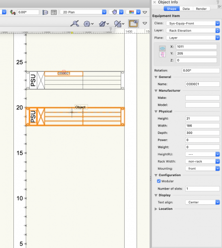
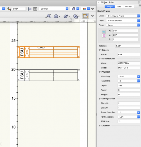
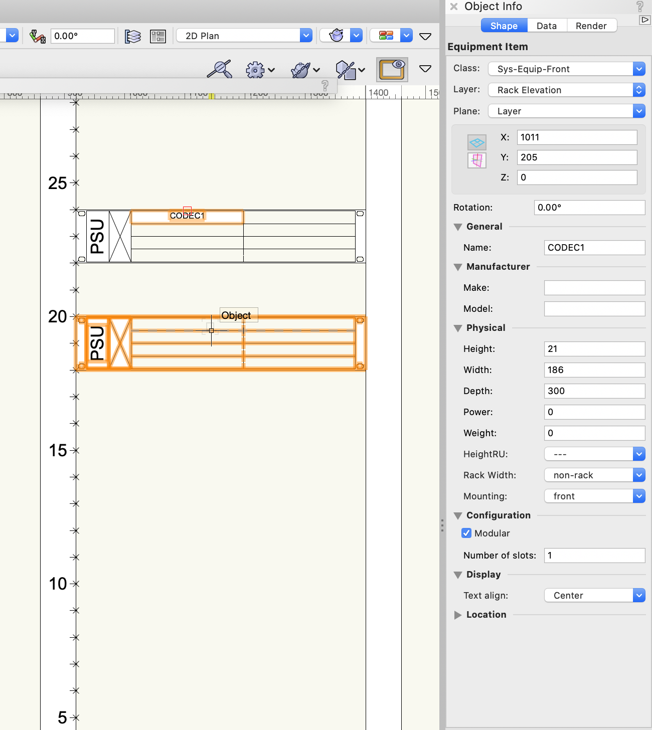
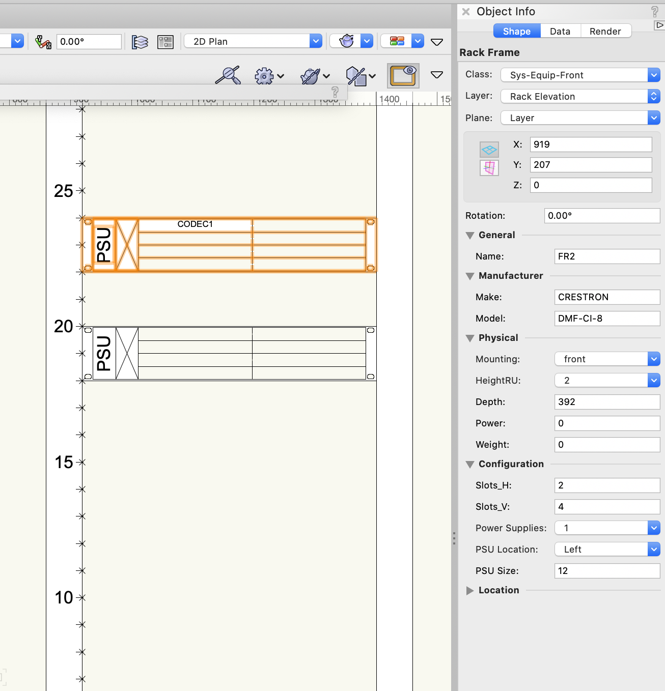
This is simpler than it seems. Get the Rack Frame tool (Layout tool set) and click in the drawing to create a frame. Head over to the Object Info Palette and configure it. For the DMF-CI-8 you would set the frame to be 2U with 2 slots horizontally and 4 slots vertically. For the codec card just set the device as modular and when you create equipment using Update Rack Elevation, the corresponding Equipment Item will be set modular - you can just drag and drop it into the frame slots and it will size to fit (you may want to set the text size smaller - Text menu). Here's two screenshots to get you on your way.
Hope that helps
Conrad
Customize Device Look
in ConnectCAD
Posted
HI @Cookie_NZ
You'd need to manually add in custom Equipment Items at this point. But I will make a note of that and see if it could be automated.
Ok that makes sense as a formatting option. Regarding custom text display we'll be supporting the ability to add text linked to parameter values in a future version.
Thanks - good discussion 🙂
Conrad