Phileas
-
Posts
206 -
Joined
-
Last visited
Content Type
Profiles
Forums
Events
Articles
Marionette
Store
Everything posted by Phileas
-
@David S Yeah that's the idea exactly you got it right this takes forever to achieve when your slab's slope has 5 or more faces though... Would be much easier if it was at least possible to substract a slab from an extrude (I only see "substract extrude from slab" in VW and not the other way around) Or substracting slabs from slabs would work as well Or simply optimizing the slab tool... I feel like there is something missing here... I'd still like @zoomer to explain his idea to use solid additions to slabs though, this sounded promising If I find a solution I'll give the exact instructions with screenshots on how to solve this kind of problem
-
I do have a solution for my problem, but it'll take hours, and I'd have to repeat it completely from scratch if I change something within the concrete slab: Make a 2D Polygon in the shape of one of the faces of the slope. Extrude it, so it's lower face is on the altitude of the drain, and the upper face on the altitude of the starting point of the slope. Copy it, so you have the same object twice. That object is an extrude of a 2D Polygon. place the copy on top of the original one Rotate it downwards, so that one side of the copy is still sitting on top of the original and the other one is intersecting the lower face of the original. Go to a top/plan view, and adjust the size of the rotated copy, so it is overall bigger than the original. (you can't do the next step immediately, because the 2D Projection of a rotated object is smaller than the un-rotated original, so solid substracting it immediately without resizing it would leave small parts of the original object unaffected)) and then use a "solid substraction" operation to substract the copy from the original object. you now have an extrude wit a top surface showing the same slope as one of the faces of the sloped concrete slab. Repeat this for every single face of the slope of the concrete slab adjust all the faces to form a "copy" of the slope of the concrete slab add volumes, so that all the extrudes you just ceated form one single object create a slab for the soil move the addition of extrudes you created underneath the soil slab, with its sloped side intersecting the soil slab. use the "substract Polygon from slab" command to reshape the slab with the extrudes you created now you have a soil slab with a horizontal upper face, and a sloped lower face following the slopes of the concrete slab. you just have to put it into it's final location. As I said, this takes hours, and if you change a single face of the sloped concrete slab, the soil slab's lower face doesn't match the slopes anymore there has to be a better way to do this... Or it's a big missing part of the slab tool
-
@bob cleaver The problem I had with 3D Polygons until now is that they have no fill in a section view. I need that soil layer to display a dirt fill when cut. I could create the "mesh" for the layer, no problem, with a 3D polyline. Vectorworks then adds the surfaces between the edges you created, but no fill. And you can't extrude a 3D Polygon like you extrude a 2D Rectangle for example, simply because the surface of said 3D Polygon is not horizontal, and vectorworks doesn't know how to extrude that (correct me if you know the reasons behind this better than me or if I'm wrong). it's just like you can't draw a 2D rectangle shape, rotate it into a 3D direction, and then extrude it. VW doesn't know how to do that.
-
@zoomer Your idea to use solid addition to slabs seems promising So I'd make an Extrude for the soil, but how do I then add it to the sloped concrete slab in order to have its lower face following the slopes?
-
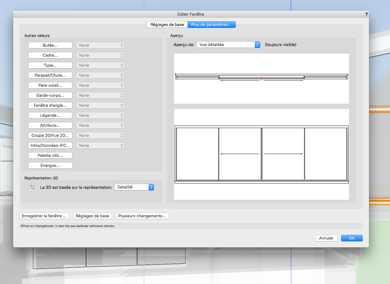
@Gadzooks Yeah I know this works for the Railing tool However, this is not possbile when you want to place the railing directly using the Window tool. You can add a railing to your window since this is something you'll obviously have to do quite often since every windowbay above the ground floor will need it, but you can't edit the posts of that railing you created, making this part of the window quite useless as soon as you want something a tiny bit more complex than the most standard railing element. I just thought it would be cool if the window tool was a bit optimised on that particular detail, so that I don't have to create the fence separately in the future 🙂
-
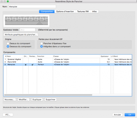
@Christiaan @zoomer I was pretty sure there had to be a way to do this using the slab tool. But I can't figure it out, which makes me feel kinda stupid. No Matter what combination of slab origin (the arrow) and tapered component (the check) I try, I can't manage to get what I want. Component number 3: the concrete slab, I want it's thickness to vary in order to create the slopes. Component number 2: the sealing layer so the water can flow, I want it's thickness to be fixed, but it needs to follow the slopes. Component number 1: the dirt layer, which I want to have a varying thickness so its lower face fits the slopes, and the upper face is horizontal. If someone could show me how I achieve that, that'd be great
-
@Diego-Resuelvectorworks I tried that as well... Either I'm pretty bad at using that tool, or it is very limited in its accuracy. I found it to be a lot less precise and performant than the window tool, I didn't try it out for too long tho. Should I give it a shot in the future?
-
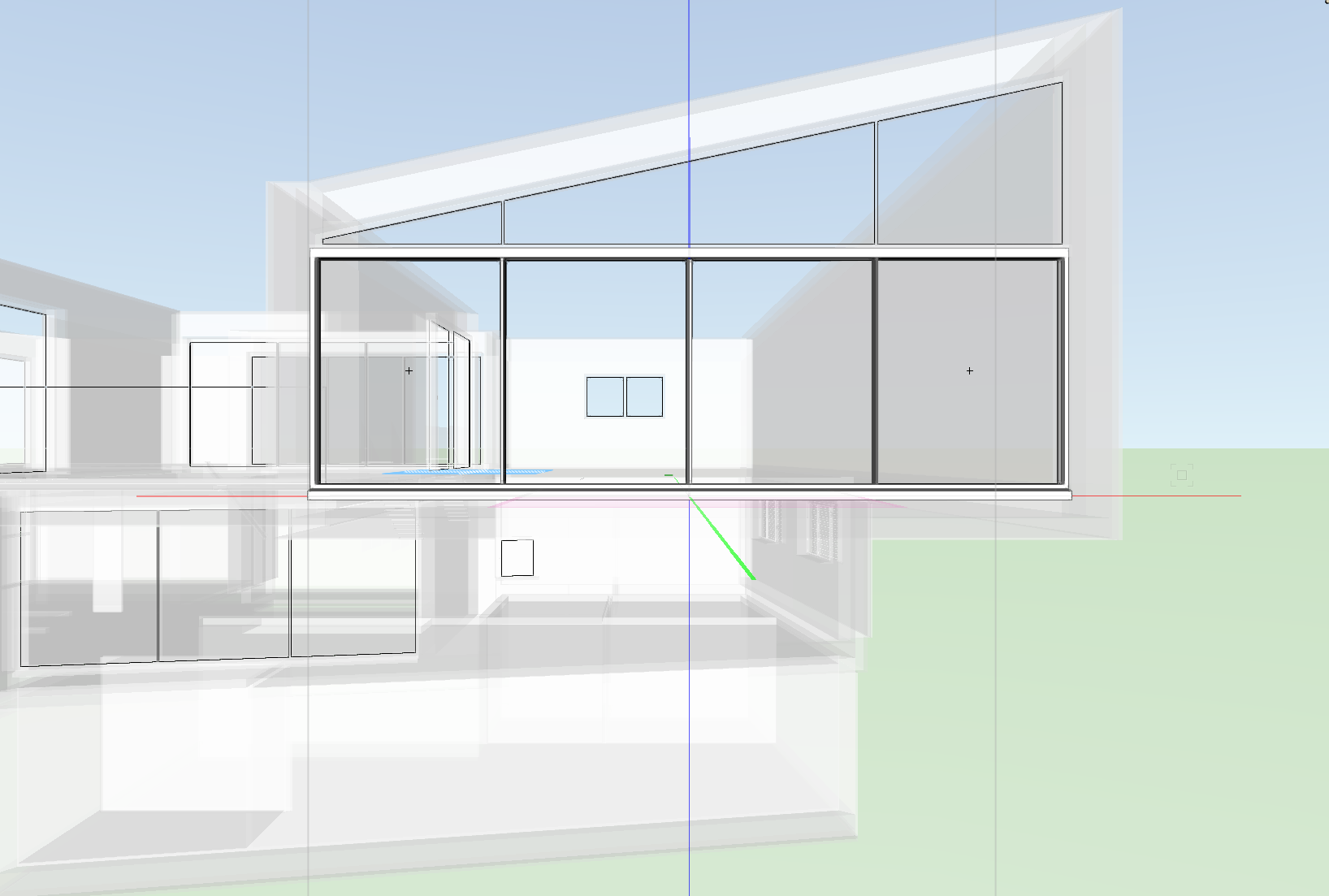
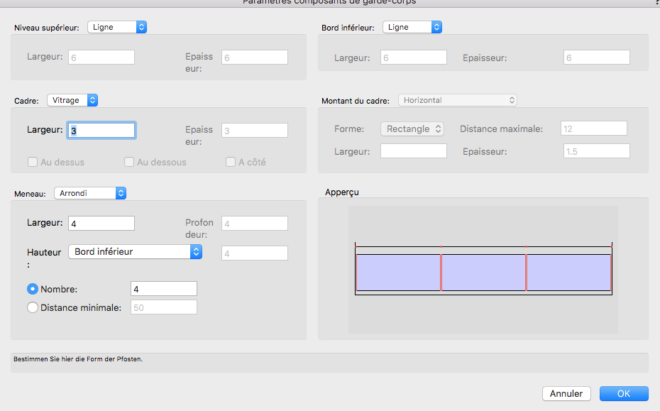
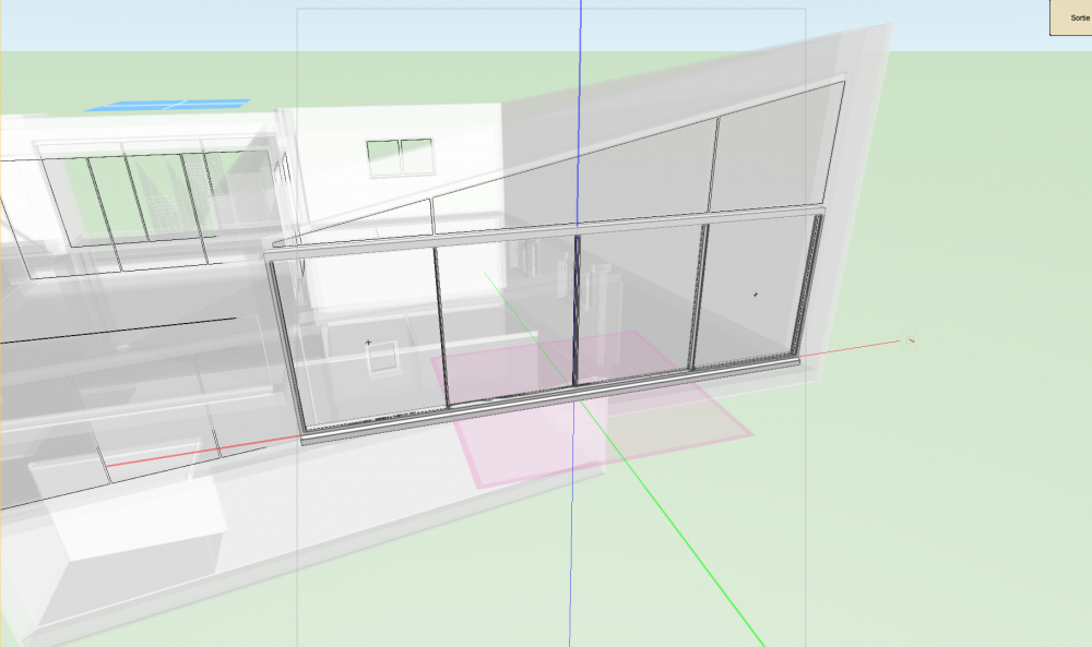
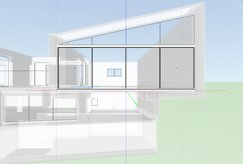
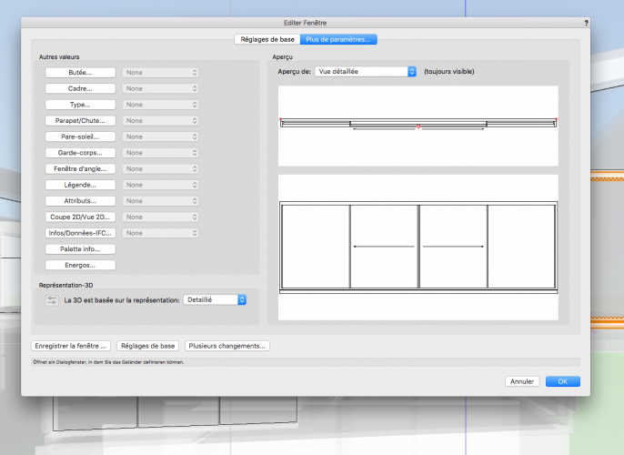
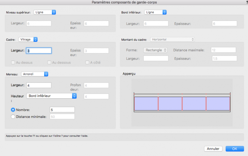
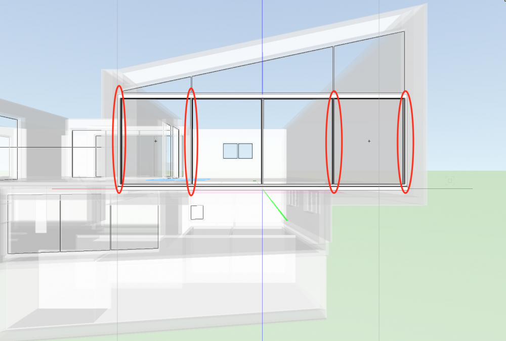
I'd like to see something added to the window tool, more precisely to the part of the tool adding a security railing to window bays: I have this giant window bay on the first floor, thus I need to apply a railing to it: The middle part of the window opens to the side on sliding rails like this (look at the arrows): I'd Like to attach the railings posts to the windowframes themselves, the parts between the posts being big glass panels in order to avoid destroying the view. These frames are set to be attachement points for the posts of the railing: That means: the spacing between the posts is irregular. and that's impossible to achieve with the window tool, forcing me to model the railings by hand using 3D Objects. as you can see, there's no way to make an irregular spacing of the posts for a railing. (Ignore the french language). For those wondering: in the "distance minimale" field for the posts, I can set a distance between the posts of the railing, but this distance would be the same for the entire railing, thus not nsolving my problem. So I'd be very happy to see VW adding the option of manually setting the space between the supporting posts of a railing in the window tool.

-
@David S take your time buddy, I have plenty of other details to fix and can just leave this slab on standby for a while, thanks for your help 🙂
-
and yes it's multi surfaces there has to be a way for VW to calculate the slopes itself
-
@David S I sure can do that. But wouldn't the extrude be the same thickness everywhere, thus not really following the slopes of the slab beneath it? I could create a polygon, extrude it to the thickness of the dirt layer I want, the create a polygon for every side of the slope I have on the slab beneath by substracting volumes between an horizontal extrude and an inclined one, inclined to match the slope I want to fit it to, and then manually place and substract every slope from my original extrude, before placing it on the slab where I want it to be. But I want a better solution, because: - If I later change the slightest part of the slab, I have to rebuild the dirt layer completely from scratch - It will take hours
-
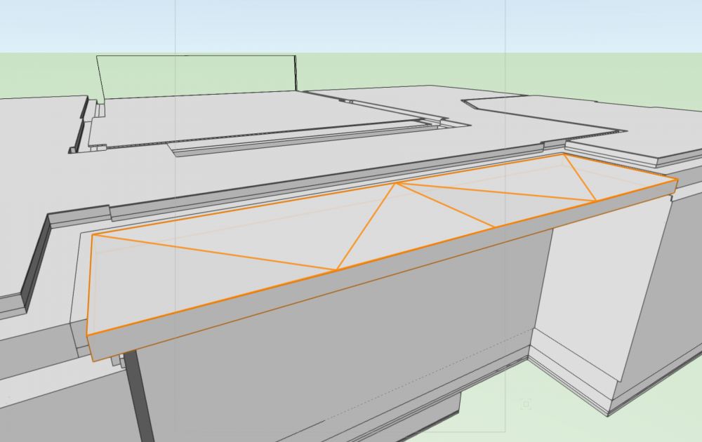
OK so what I'm trying to achieve is: I have a sloped slab (slopes for water draining purposes). This slab, made out of concrete covered with a thin sealing layer so the water can flow, is set to be covered with dirt in oder to have a vegetated surface. The surface of the dirt however isn't supposed to be sloped in the same way the supporting slab is. I want it to be even, and the thickness of the dirt layer to vary to match the slopes beneath it. How do I do this?
-
window/door in horizontal section viewport issues
Phileas replied to drelARCH's topic in Architecture
@drelARCH ok... sorry I couldn't help... I have no idea what the problem could be -
window/door in horizontal section viewport issues
Phileas replied to drelARCH's topic in Architecture
@drelARCH Are the rotated doors and windows standard objects made with their respective tool? Or did you make them symbols? I experienced a similar issue with windows on a project of mine, and rotating the corresponding objects 90 degrees in the editing window of the symbol solved the issue -
Wish List for Slab Drainage Tool
Phileas replied to Phileas's topic in Wishes Granted / Issues Resolved
@Hans-Olav Embarrassing confession time: This is exactly what I wanted to do this whole time, but it never actually crossed my mind to try and right-click the blue handles. I right-clicked the drain probably 250 times, but never thought of trying to click the handles 😞 I feel stupid lmao Thanks man you saved me again, if I could I'd like your comments ten times 😉 -
Wish List for Slab Drainage Tool
Phileas replied to Phileas's topic in Wishes Granted / Issues Resolved
@Hans-Olav How do you edit the endpoints of a slab? I've never seen a dialogue box where you can set a thickness for a particular spot of a slab -
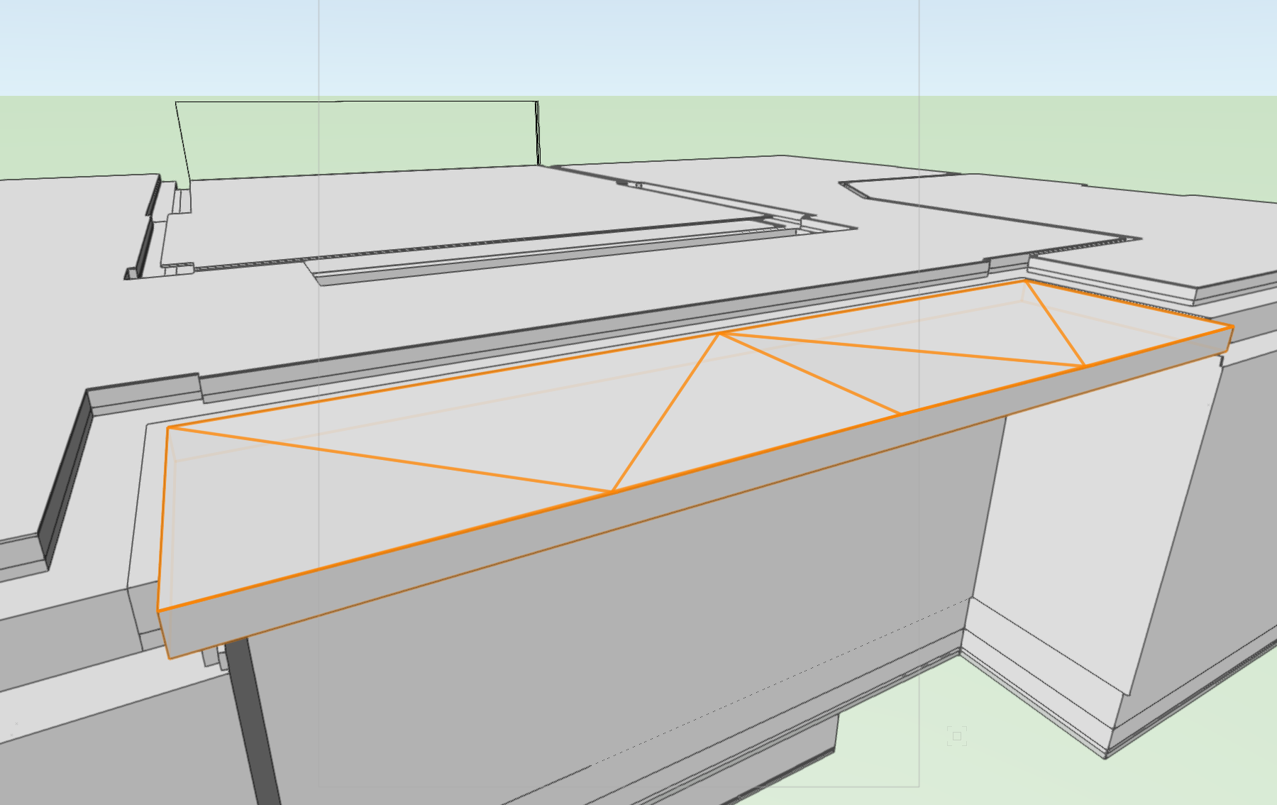
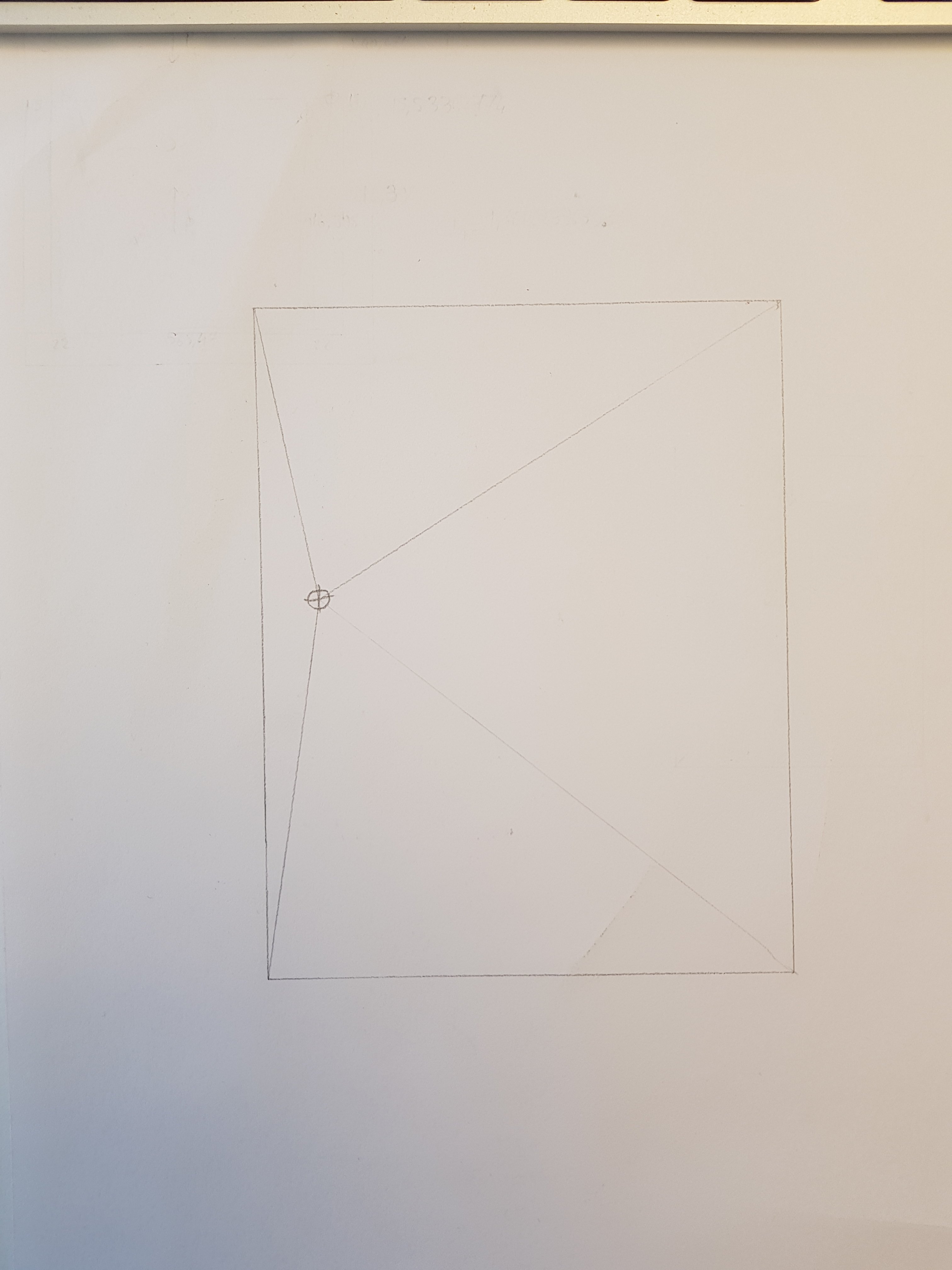
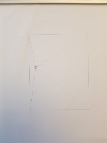
Hey so I'm working on the water evacuation system of a terrace, and I've encountered a problem that I believe is impossible to solve with the slab drainage tool: This is a quick sketch of what the slab looks like. Now here comes the problem: This terrace is on the first floor, so the sides of the slab you see here need to be joined to the concrete slab of the first floor of the house. To do so without creating an insulation problem with the heated rooms below, this joint needs to be done using "thermal consoles" (or I don't know how you call them in english, basically 8cm thick insulation panels with steel beams, capable of carrying the weight of the terrace just like normal concrete). Thing is, these thermal consoles have a fixed height, and can only be joined to a slab with the exact thickness matching this height. So all the sides of my terrace slab need to be exactly 22cm thick. So what I would want to do in VW would be to somehow tell the program "OK so all the sides of this slab are 22cm thick, the drain is 7cm lower, please adjust the slopes so they match these requirements". With the slab drainage tool, I can adjust the desired maximum thickness value of the slab, the altitude of the drain, and the slopes by hand. The point is, I have no way to ultimately fix the thickness of the edges of the slab and have the slopes calculated by VW, I can only fix the slopes and then have the thickness calculated, which is useless to me here. So if anyone has a solution for this (other than creating a 3D-Object counterpart to my slab and then use the "substract 3D Object from slab" command), please let me know. If there is no real solution, then I'd like to know where I can add this feature to the wish lists for future versions of VW. Also for the wish list: The automatic cotations of the slopes that are generated by the slab drainage tool are impossible to move around properly, and the only way to edit them somehow is through classes. I'd like to be able to edit them like normal text characters, that would make everything much easier.
-
@Diego-Resuelvectorworks Worked perfectly, thx 🙂
-
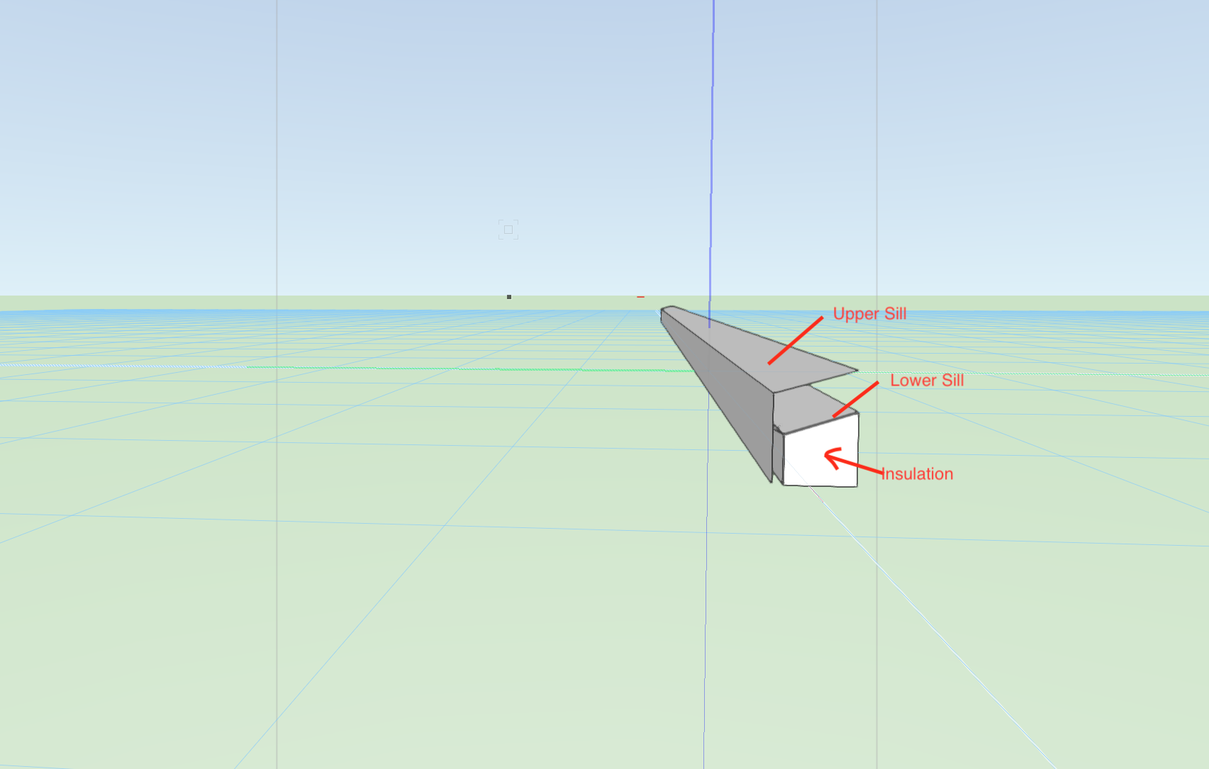
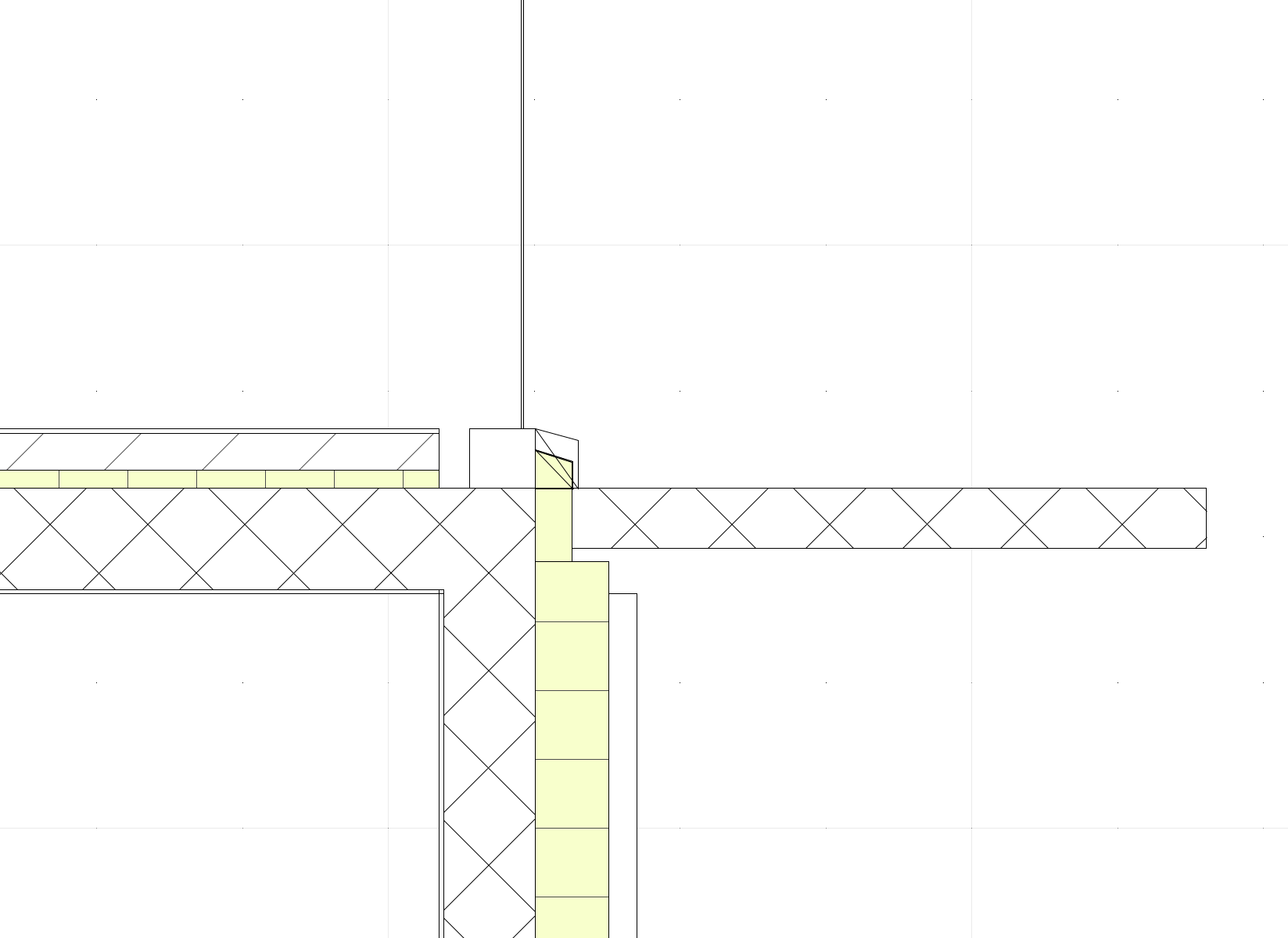
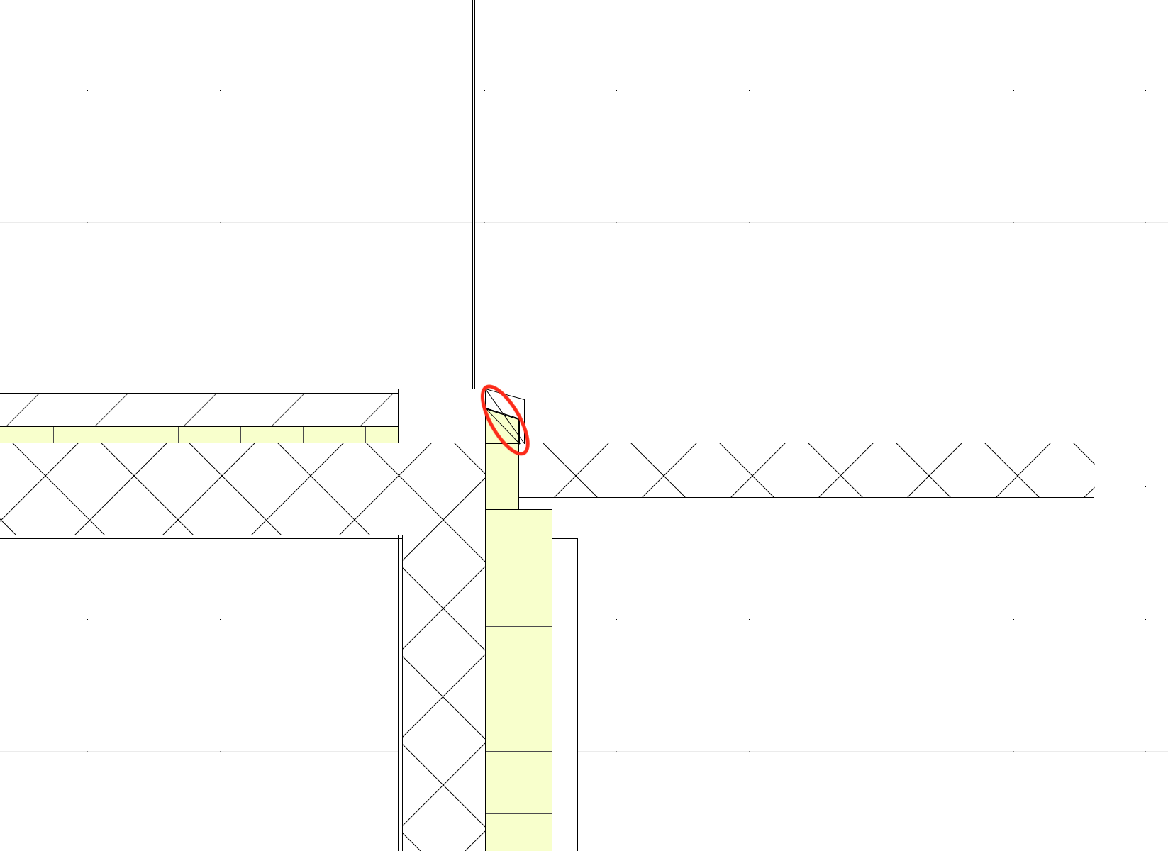
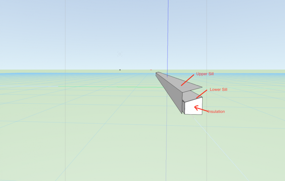
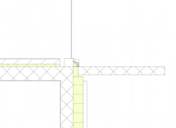
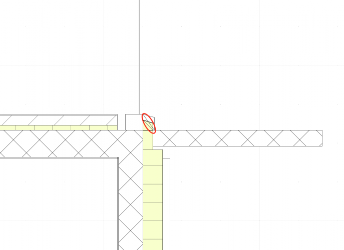
Hey so I have a pretty specific window in my project that I had to create using 3D Objects because the window tool wasn't powerful enough to do it. Which means I can't add a sill to that window as easily as with the window tool. For aesthetic purposes, this window is set to have a double sill (one underneath the other, so that the condensation water from the window is evacuated, and an upper one that hides the lower so it seems like there is no transition between inside and outside (see my attached screenshots)). In order to keep the building well insulated, the lower sill is set to be lying on insulation material and screwed to the window frame, and the upper one simply screwed to the window frame: Here's a 3D view of it: My Problem is the result I get in a Section view: VW renders a line that links the part of the sills, which makes the whole thing look wrong: unfortunately I can't get these line to disappear... some help would be appreciated
-
@Markvl Lucky me I have 2018 lol 🙂 Made my life a lot easier since @Hans-Olav showed me this feature
-
@Hans-Olav thank you very much my friend 🙂
-
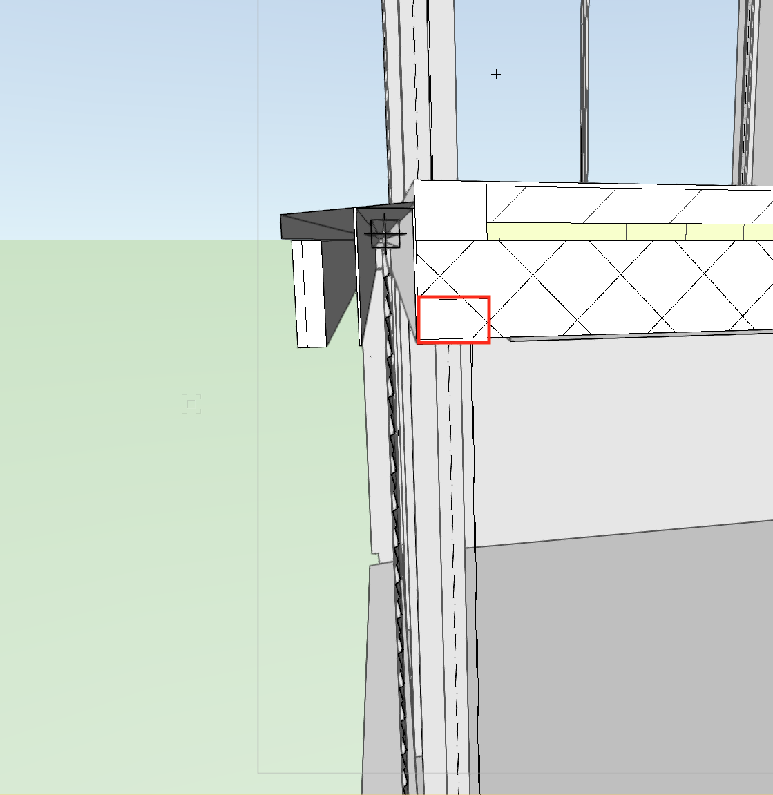
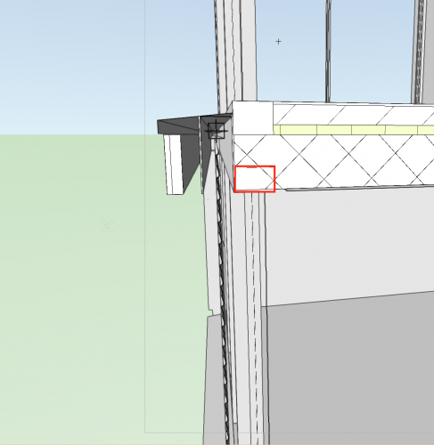
In the project I'm currently working on, I've got a window whose guiding rails are inserted in the concrete slab above. I wanted to know if there was a way to cut a corresponding hole into that concrete slab, without using this tool: , because it cuts through the whole slab, which is something I don't want. Here's a screenshot with the part of the slab I'd want to cut highlighted: I know I could create an extrude in the corresponding rectangular shape, place it where I want the hole and use "substract volumes" to get what I want. Then I'd have to assign a fill to the new 3D Object my slab became, so that it still appears as concrete in section views. The problem with that method is that the resulting entity is not a "slab" object anymore, so any reshaping of the boundaries would become quite time-consuming... I wanted to cut that hole without changing the object style.

-
@Hans-Olav worked perfectly 🙂 I wanted to thank you for helping me so much recently, I'm quite a newbie to Vectorworks and still learning
-
@Hans-Olav Thank you very much! Do you happen to know how I assign a fill to a 3D Object?
-
I wanted to know if it is possible to set the options of a 3D Object (an extrude for example) in a way that the Extrude would show a fill in a vertical section view, like floor slabs do.