


Claes Lundstrom
-
Posts
228 -
Joined
-
Last visited
Content Type
Profiles
Forums
Events
Articles
Marionette
Store
Posts posted by Claes Lundstrom
-
-
19 hours ago, tringas1 said:
More Progress with the no rail loft surface.
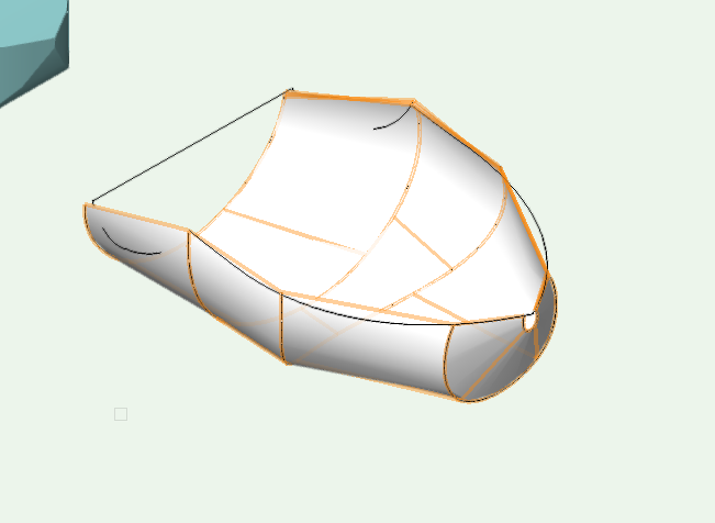
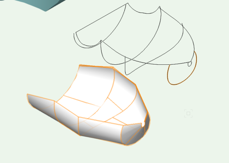
A much easier way to build for example a fencer is to just generate a clean basic shape, in this case the entire side panel of a car, and then trim out the opening with simple extrusions from the side. In the case a circle with a rectangle extension (add surface) for the wheel arches and a double line polygon for the door gaps.
-
12 hours ago, Pat Stanford said:
Claes,
Does TouchCAD offer the features you are saying VW is missing?
In this case, yes, but my point is that it can also be said about many other reasonable capable NURBS based modeling programs too. VW could have been so much better with just a few minor tweaks.
-
After having played around a bit with this, I agree that lofting NURBS curves is the way to go.
VW is however probably not an ideal tool for such modeling. It can be done, but it's very difficult. Doing proper proper panel fairing requires a ot of micro adjustments, and VW has two user interface weaknesses in that respect: 1/ You can't nudge any given selection of control points with the arrow keys. 2/ You can't edit more than one patch at the time.
-
 1
1
-
-
On 2017-10-20 at 8:40 PM, tsw said:
In addition to the suggestions in the thread Andy linked, you could try applying a transparent texture to your object then duplicating it in place and removing its fill. It will then display as a wireframe in OpenGL (albeit without anti-aliasing, so the lines are a little jagged).
It's a bit of a workaround (and makes further edits a little tedious), but it kind of achieves what you're going for. Here's what it looks like in a rendered viewport:
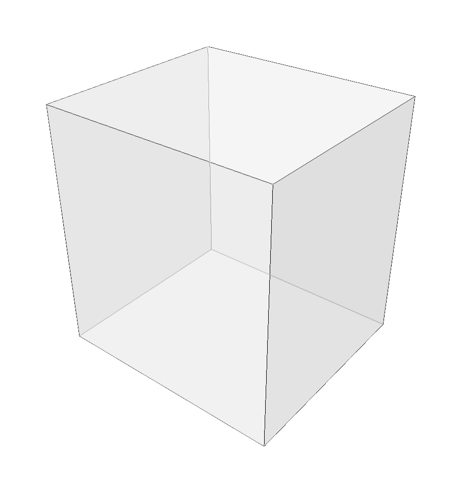
I also (often) use this rather clunky method to bypass the problem. I actually bug reported this some years back, bit was informed that it works as designed.
Let's say that we agreed to disagree whether this restriction was a good thing. To me, it makes no sense to delibetrately restrict a possible way for the designer to do their job as they like.
-
1
-
-
Provided that the data are accurate enough, a simply point cloud should work fine in the DTM to generate a 3D terrain model. What accuracy are they claiming ?
Speaking of drones, has anybody used one in combination with a photo modeling program (such as PhotoModeler) to extract terrain data ? I assume a decent drone model such as the Phantom 4, having a good camera 4K video and is able to extract decent stills. I have used PhotoModeler and GoPro cameras to extract data used for creating boat covers (well over 200) and it seems to work fairly well, so that's why I am curious.
-
1
-
-
On 2017-10-22 at 5:57 PM, Ethan R. said:
Hi Claes,
Which program are you using that has this option? Is it sketch-up ?
TY
Ethan
No it's not SketchUp (have it installed somewhere but never use it as it never adds anything to my work).
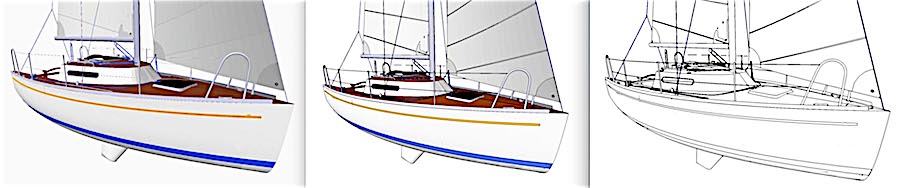
Besides that, my point is that it would be nice if VW could make use of the algorithms found in OpenGL for extracting edges. As an example, I imported this 3D polygon based model in the pictures into VW. All rendered in OpenGL only. No edges to the left. With edges in the middle. All colors set to white and increased the light a little to the right, and there we have a nice outline drawing at almost no effort. Imagine that we could compose those lines into plain filled polygons.
-
19 hours ago, MullinRJ said:
Claes,
When using Add Surface, I have found that limiting the selection to 200-400 objects is optimal for throughput. There appears to be an exponential slowdown based on the selection count. Waiting for 1000+ objects to ADD is intolerable for me, so I select small groups and Add Surface repeatedly. When done, I select the whole object and Add Surface again, but this is invariably a significantly reduced object count. If the resulting reduced object has over 1000 pieces, I'll carefully select contiguous pieces and add those.
Using this approach I can be done with a 30k object count in under 5 minutes where VW night easily take 30 minutes to a few hours to complete in one pass.
Raymond
Yes, I totally agree that using thousands of polygons does not work. Ideally, it would be great to have a special display mode only showing outlines, like in OpenGL but without the shadings. I use the Add Surface, Combine into Surface, Compose features a lot as I often import models looking like this. Luckily for me though, the exporting program has an option to just export the outlines, where each panel comes in as a group. The only thing I need to do is therefore to ungroup and Compose the object and job done. Takes a minute or two of minutes to do the job. So, on the wish list in VW would be to have such a feature.
-
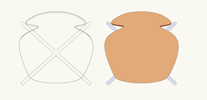
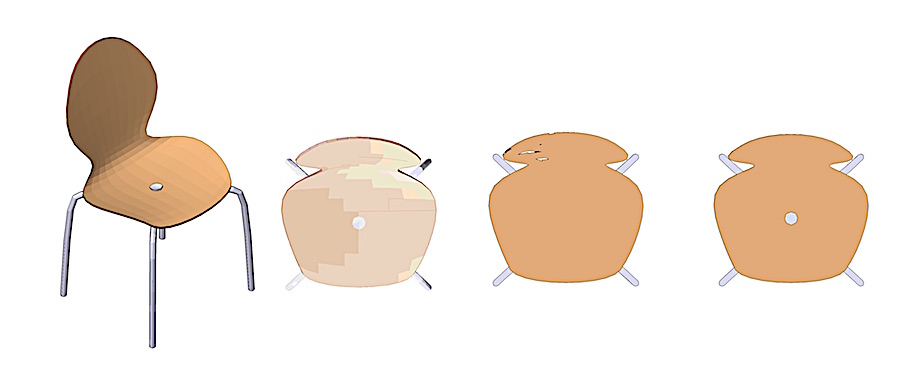
No quick solution to this. As an example, I took this fairly simple chair, and did as follows:
1/ Original (left) (Symbol to Group if it's a symbol) -> Convert to Group -> Convert to Polygons with Hidden lines on. Generates many polygons.
2/ Original (left) (Symbol to Group if it's a symbol) -> Convert to Group> Convert to Polygons with Hidden lines on-> Add Surface. Probably took longer than it took to model the chair in 3D.
3/ Original (left) (Symbol to Group if it's a symbol) -> Convert to Group -> Convert to Lines-> Ungroup-> Remove all inner lines-> Assemble using Compose or Combine into Surface. Takes a while but probably the best result.
4/ Simply trace the model manually. Depressing but it works, though it is slow (probably more than the five or six minutes it took me to model the 3D original.
-
1
-
-
Not sure why you talk about the file format .3DS, which is a file format by Autodesk 3D Studio Max and has nothing to do with Sketchup. This file format is primarily used for communicating 3D files containing graphics and textures for rendering purposes. I use it mainly for exporting to my external rendering programs. The generic Sketchup file format is called .skp and can be read by VW. Exporting to Sketchup should be possible in several formats, such as DXF/DWG, 3DS, WRML, OBJ, FBX, IFC, etc.
-
1
-
-
19 hours ago, zoomer said:
When I use any kind of Modify Tool Version and want to add additional Vertices to a Polygon.
I want to be able to grab a Polygons Segment everywhere along its Edge.
Not just at its Vertices
(Where there is no feedback in which direction the new Vertex is possible)
(Especially at the Ends of "open" Polygons, like Site Model Source Data, where the
result is super arbitrary)
or Midpoints only.
(Which may be very far away from where you focus on by your needed zoom level)
Yes, would be handy if adding control points in a polygon would work more consistently, for example always upwards or downwards in index direction, and with the little red direction arrow that you can turn on in Object Info being on by default when working with this tool, so that you know the direction. As it is now, the only predictable way is to use midpoints.
-
2
-
-
On 2017-08-10 at 11:30 PM, michaelk said:
Not really. VW doesn't have a unit of weight. So it doesn't know that a kilogram is 1000 grams or how that's related to our antiquated pounds.
So the weight information that is stored in all of the instruments is actually just text.
But you can make your own record format that attaches to everything with a weight field in the same units as a real number instead of text and use that.
Let me know if that doesn't make sense. I have an example here somewhere I can dig up and clean up.
I disagree. It can be calculated using the surface area of the tubes included. Sorry for bing a bit metric here, but let's say that the truss consists of for example aluminum tubes having a wall thickness of say 2 mm. The denstiny of aluminum is 2.7 kilos per liter, and one liter spread out over 1 square meter has a thickness of 1 mm. From that follows that a material thickness of 1 mm and a surface area of one square meter has a weigh of 2.7 kilos. 2 mm = 5.4 kilos and so on. So, you basically only need to multiply the density of the material with the wall thickness and surface area in square meters to get the weight. If the truss consists of materials having different material densities and wall thicknesses, you can create a database where one field simply has the density multiplied by the wall thickness, and then multiply that by the surface areas of the respective in a database spreadsheet. This can be elaborated even further by also calculating the center of gravity in three directions, or simply adding a given point weight for a given element, for example a fitting element instead of using the surface area method. I use all these methods extensively and find them very handy.
-
1
-
-
6 hours ago, Bruce Glanville said:
Thanks very much for all your feedback- that isn't the first time I have seen people recommending against Makerbot, I would really appreciate any specific recommendations for 3D printers for architectural models- I am keen to be able to print 1:100 form models to complement our VR presentations to clients for new and renovated dwellings and also 1:200 site models for development work.
Whilst experienced in using Vectorworks (I started at Uni in 1998 and have been a user of the various versions since then) I am very new to 3D printing (at Uni we used flat bed routers to create some fairly interesting models from laminated solid timber blanks), it does surprise me that more of the CAD manufacturers haven't given more thought to what seems to be (though I'm sure in practice aren't) simple changes that would benefit greatly like the scalability of STL's etc, again thanks for your feedback, much appreciated.
Cheers Bruce
I guess an option to 3D printers would be to use a print and cut machine.
At an entry level, and if you just want to try it a bit, you have for example the Silhouette Cameo, which allows you to cut up to say 200 grams (not sure how thick though) of photo paper and about a foot wide, and has simple printed positioning dots added. The referencing between the "picture" and the cut layout is controlled by these reference dots, using an optic eye in the machine.
Admittedly, you still need to assemble the model, but on the other hand you get realistic textures and colors and it cuts very detailed models. Printing and cutting is usually much quicker than 3D printing though requiring assembly.
Transferring models from VW works OK as long as you keep the contours as contours instead of with fills for the cutting part. Many cutter drivers seems to have problems with VW's polylines with holes inside, which however isn't VW's fault.
I use both 3D printers and print and cut machines and both have advantages.
-
Scaling should be added to the OBJ format too, as it's also used for 3D printing.
-
On 2017-05-21 at 10:05 PM, Robert Anderson said:
Right now, the Vectorworks "Unfold Surfaces" command can do flattening only of simple (singly-curved) shapes. TouchCAD can do unfolding of complex shapes. (You'll probably have to convert your subdivs into other primitives before you export.) You can look here:
Yep, do that a lot in TouchCAD. This 3D Elvis model is about 1.5 meters. Fabrics skin with printed texture.

-
8 hours ago, Pat Stanford said:
If this is important and worth money, check out TouchCad. http://www.touchcad.com
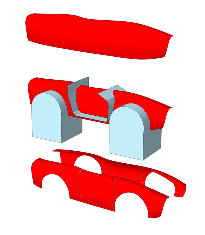
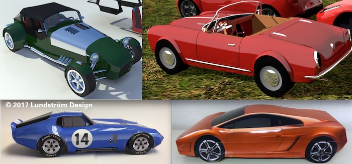
Since you mention TouchCAD. Yes, you can do more advanced things with it. Here is a recent example, a 1964 Shelby Cobra Daytona Coupé to be be produced in two copies in scale 1:1 in fabrics for an exhibition. It was a little less expensive that getting the real thing. One was recently sold for 7.25 million dollars... The pictures show the 35 piece kit as flat with super high resolution photo realistic unfolded textures, and as a cardboard model.

-
1
-
Loft Surface
in Solids Modeling
Posted
Could be, though a simple texture with transparency and bump map on a comparatively simple shape would probably be more efficient, as much of the work is then done by the video card. Solid modeling may generate huge files, which lags modeling and rendering speed. Should therefore be used wisely and with moderation.
In the example, I converted a sphere into NURBS, chopped off the bottom a bit unevenly and the applies a simple texture I created based of a simple leaf shape, which I repeated randomly while making small variations in color and shape in VW 2D. Easy enough. Left picture as it looks on OpenGL and right in Renderworks, where the bumps are noticable .