Gadzooks
-
Posts
509 -
Joined
-
Last visited
Content Type
Profiles
Forums
Events
Articles
Marionette
Store
Everything posted by Gadzooks
-

Find which VWX file a PDF was generated from
Gadzooks replied to John Whyte's topic in General Discussion
There is free/cheap software that will allow you to change the default meta data as seen with the pdf 'inspector'. Your pdf reader (Mac or windows) may already have this. Just get into the habit of adding the additional info before you file on the server. The info will then be available to a later reader when wanting to find the parent file. Staff must always do it before filing though! I'm not techie myself so can't suggest a more advanced computing solution. I just work with the tools I have! Alternatively, and useful - as its far less 'techie' and more up my street - just arrange your back-up server hierarchy with folders for each individual drawing produced for a contract (obviously within a 'contract' folder). Then when you produce pdfs make it the company rule to place them in the correct folder (so its already with its source VW file) so history/link can be seen. They can be aliased (Mac) or shortcut (PC) so you can arrange them in another workgroup folder for looking up (say) useful roof details - where you find the detail that you like and then can open the vw file it was sourced from. Once again it relies on staff being careful! Hope I've understood your problem correctly and that this might help. -
I think I've finally cracked this one... Kevin (thanks for sticking with this issue), it is as you say, something to do with the layer plane settings and I believe this is it...... I assume you have opened a 'blank' doc and tried the exercise without problems. This seems to work because the defaults on the layer you are drawing on are 'out of the box'. Most users will change the settings as appropriate for their Industry. Try this - In the layer plane settings, set the layer elevation to anything but the default 0. Keeping the view to layer plane, try the square>2 lines>group flip test again. It splits! This is why both you and Marissa have (correctly) concluded its a specific file issue. I had set my blank.sta file to values above zero. On testing the options, it seems its the height above ground plane rather than other parameter - (say) the layer wall height - that influences this. BTW - if you check the layer from front view, you will see the geometry has been drawn upon the zero ground plane (as you would expect with 2D creation) - so nothing untoward in that respect. I also find - in limited testing - that the culprit is the rectangle as it doesn't seem to happen with other shapes. Do you find this? If not, please let me know what your findings are. If yes...... @Marissa Farrell I believe this is a bug. Maybe the one you were talking about? 2D objects drawn on the layer plane should 'forget' any height reference the plane has. Thanks both.
-
You're correct on that one - a new (blank) doc and it works as it should!! However, starting again with my blank .sta doc it is still a problem, so it does seem the issue is with that. I'll have to bin it. OK - not entirely sure were I go on this one - I'll make some changes and try to bottom it out what makes it fall-over, but weird as to how the document setup can have such an adverse affect. I'm obviously just learning the quirks of VW Thanks for your help
-
surely.. problems with group.vwx
-
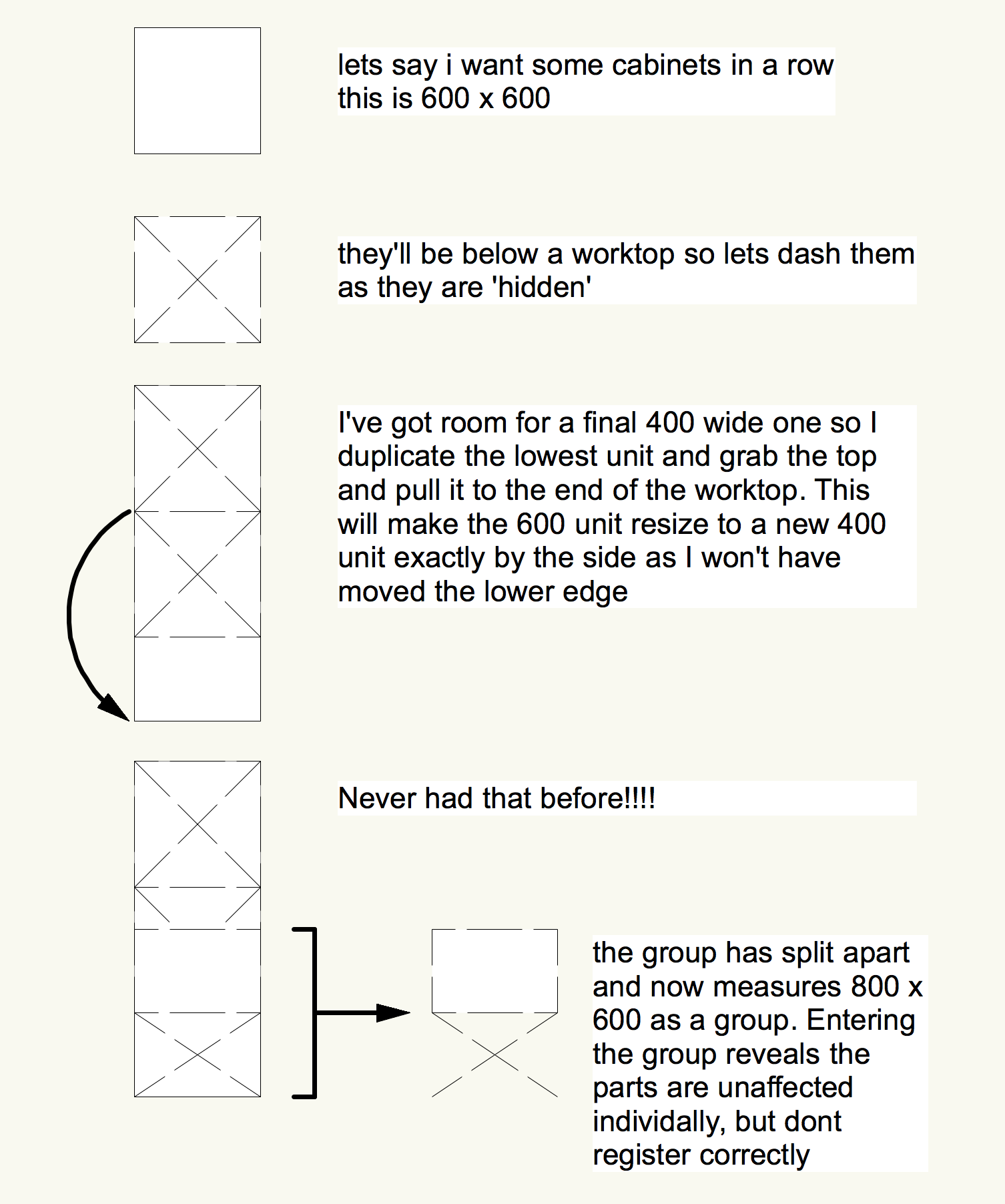
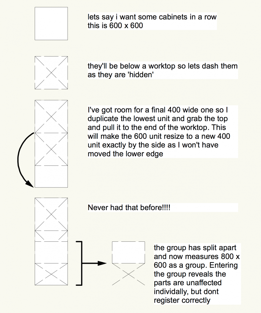
this are the details before and after.. do you still need the file?


-
Thanks for taking a look at this Yes just a 2D rectangle and two lines which behave normally when pushed and pulled away from the centre of the group. But...Are you pulling the 'top' of the group over and resizing past the 'bottom'? To be clear, using the handles take a side fully across and past its apposing side (Imagine if it were 3D you'd be flipping it over) This inversion/flip is what seems to cause the grouped items to lose their geometry - where it shouldn't. Or or at least on my setup!
-
I can't work this out...is it me? My previous use of VW has always allowed a group (having been formed by placing several items together) to remain in their relative positions to each other (thats what a group is yeh?). This allows them to be squashed and shaped as 'a whole'. I have used this a lot as a way to make things fit - its a very useful side feature. This isn't happening with 2017 SP4 on a Mac I'm assuming its me - so don't come at me too hard.
-
Good find Christiaan. I see the webpage allows you to 'save' the blend more than once to a series of images - all at the same mix % with a randomised result. A bit more work, but this would allow you to build a larger sample image as the basis for your texture, thus minimising the dreaded image repeat on larger panels. The mortar colours don't impress, but if you choose a colour that can easily be colour picked in PS (almost an alpha) you'd be able to replace with your choice of colour from your chosen supplier. Photoshop here I come.... Designer 2017 SP4