


BG
-
Posts
382 -
Joined
-
Last visited
Content Type
Profiles
Forums
Events
Articles
Marionette
Store
Posts posted by BG
-
-
Have the same issue printing PDF's created in VW on an iMAC. Printing the PDF's using ACROBAT prints the text in Gibberish, however when the same document is printed using PREVIEW, the PDF's print fine. So I always print using PREVIEW obviously :-)
-
Would it not be worth simply replacing the sheet border tool with the VAA Title Block tool that Ozcad has created? It seems like it already has the features being requested.
Just a thought.
-
 1
1
-
-
Hi. That's a shame.
Have you e-mailed Julian at Ozcad? It might be a useful feature to add so that some of the data from the 'Schedule Data" tab could be displayed with the ID.
Cheers
-
Hi Josh
I'm pretty sure there is a way to show more information. Have you viewed the Windoor Tutorial video? This details how to customise the ID's etc.
-
1
-
-
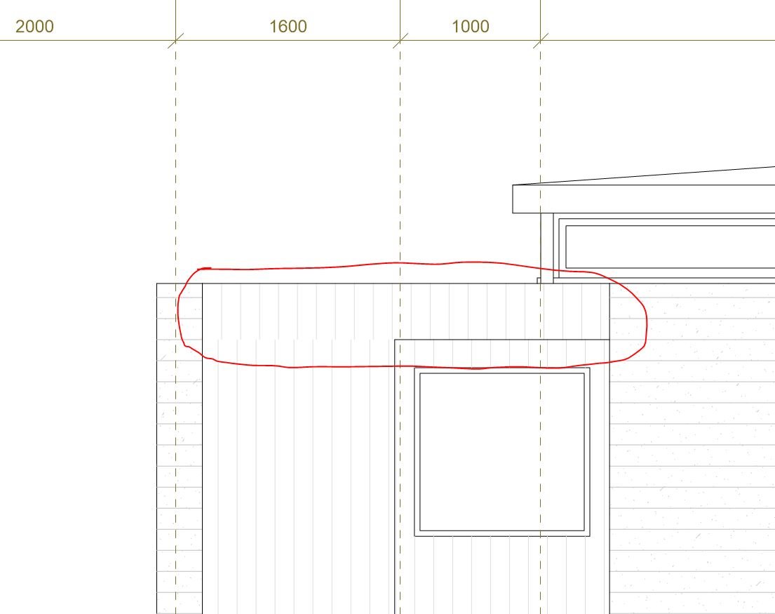
Using World Z didn't help with some wall hatch alignment issues we had. The origin of the wall hatches/textures need to be easily adjustable. The cladding is always set out from a particular spot/level. It's never random.
-
Cool, will check that out. Good spotting.
-
Hi Josh, we've had the same issue. Be great if the origin could be set for each texture so that aligning the textures & wall hatches was easy & adjustable. Hopefully someone knowledgeable can answer this.
Cheers
-
Hi. It's a surface hatch associated with a render texture. Both hatches had 'auto-align plan' selected. I adjusted the hatch on the wall above using the 'Offset H' field in the OIP and that seems to have it close enough. I was really just wondering if there was a "correct" method to align surface hatches.
Thanks
-
Hi
What is the correct way to align the surface hatch on a wall that is above another wall?
Thanks
-
Hi
A simple question regarding releasing layers.
I have a number of layers checked out.
How do I release say, just one layer?
When I choose release in the 'Layers' tab, it releases all of the layers?
Thanks
-
Yes. On numerous projects. I've contacted Ozcad about it on a couple of occasions, but they couldn't provide any solutions.
When the ID's disappear we haven't been able to find a way to make them visible again.
It was happening prior to VW2016.
It's really frustrating.
-
If you select the site model & give it a solid white fill in the attribute palette, it will show as solid in a section viewport. Still shows as hollow in clip cube though.
-
Hi
Yes, the extrudes are separate. The whole face of the extrude always moves when push/pulled (as expected), but I can't see how to tell VW only to push/pull the piece of the extrude that extends beyond the other extrude?
I'm missing something.
-
Hi
I've watched this video
and I really like the method shown to trim extrudes to each other.But - I can't seem to get the push pull tool to work like shown. It always moves the whole face of the extrude. I have the 2nd mode selected (Move Face Mode)
Any tips on how to replicate this method?
Thanks
-
Ignore that last post, I figured it out. The site model is on the none class which has no fill.
Thanks again.
-
Cool thanks, which class in particular did you have to make solid?
-
Hi
I have a section viewport of my site model on a sheet layer, to create building elevations. This works well, but the lower walls of the building which go 'through' the site model are visible - it's like the site model is transparent.
I have hidden line selected as the rendering mode.
But when viewing a side view of the site/model on the design layer in hidden line view, the site shows solid as expected.
What controls the site transparency in the section viewport?
I've attached an image showing what I mean, plus the VW file.
I'm sure it's something simple.
Thanks
-
Thanks
Under the wall attributes there are two options.
1. Use Wall Line Attributes
2. Use Component Line Attributes
My wall styles had option 1 selected.
I changed this to option 2 and the wall caps appeared so that's good.
With option 1. When you have a wall made up of various components, what 'wall line' would this be referring to?
With option 2, which component does VW use to cap the wall? The core component?
-
Hi. This might be user-error, but when you have floor plan using walls with components - say a typical timber wall with plasterboard lining each side, when you turn the class off for the lining, the wall cap disappears on the ends of walls and at openings.
Is there a way to keep the wall caps turned on?
Thanks
-
Hi Benson
I don't find that the tilde disables all snaps. I wish it did. With the tilde held down, when you move your mouse over an object, it still highlights and can be selected, just not on a corner or edge etc.
Try this, have a large rectangle solid filled, draw a smaller object inside this rectangle. Now try dragging a marquee around the smaller object to select it. Can't be done, as it keeps selecting the larger rectangle, even with the tilde pushed.
B
-
Hi Jim
We have held off installing 2016 due to the high number of issues, bugs etc a lot of people have been posting messages about.
It's just been released I know, but it would be good to hear how stable 2016 SP2 is.
Other feedback would be helpful too.
-
Totally agree, this has been wished for, for a long time. And the horizontal top face of walls that zoomer mentioned is also right up there on our wish list for a sloping option that meets the roof.
-
Hi
We are using a keynote database for multiple files.
We may be using the callout tool incorrectly, but it seems that once the keynote is placed & the note is pulled from the database, it is now un-linked from the database i.e. the note can subsequently be changed without it changing the note in the database. You then need to manually update the database if you want the notes to match.
On multiple files, you then need to go and do the same process in the other file(s). This is prone to error.
Question. Is there a way to have the notes permanently linked to the database & the only way to change the note is to change the note in the database? Therefore any changes to the notes in the database would be reflected in any file that uses the database.
Thanks
-
Hi
Looks like a lot of nice new features, but got to agree with Altivec, it would be preferable, rather than focussing on new niche tools, a focus is made on fixing and or adding basic functionality that has been missing for some time. Others can probably list a lot of items, but for us architects, why do we still wait for sloping walls to be added? and the number of times people talk about the stair tool...then there's 3D hatching - when adding hatching to walls & roofs, there is no option to individually specify the start point for the hatch on each surface. This basically means we often can't use that feature.
Thanks

Updating All Callouts From Updated Database
in Wishlist - Feature and Content Requests
Posted
I'd like this confirmed too. We use Keynotes from a database, and unless we're using them wrong, once the keynote is placed, it is no longer linked to the database. If the keynote description changes, we have to update the database to match. We think it should work so that the keynotes are always linked to the database.