domer1322
-
Posts
595 -
Joined
-
Last visited
Content Type
Profiles
Forums
Events
Articles
Marionette
Store
Everything posted by domer1322
-
I have an old file (a 3D model of my own house) that I've been updating or changing for years. I notice that my door plug-in objects do not allow me to assign door hardware to them. That is, I click "settings" on the OIP then in the door dialog box I pick 'hardware' and the area where there is normally a list of all the available hardware sets shows an empty box. When I click on the box "include hardware" it makes no difference. I have some hardware sets already in the resource browser of this file. I tried to "update plug-ins" as well as "reset plug-ins" but it made no difference. I do not have this issue with other files. It seems to me I have to tell VW that there is a hardware file in the 'libraries' folder, but I can't figure out how do that. Help .... please .... (I'm using VW 2015 but I hope you'll consider replying even if I'm using old software).
-
Boh: thanks for the reply. I needed someone with real skill to verify that it isn't possible. I suppose sometimes the 99% technique might be OK, but I want to render it in OpenGL without seeing the line. Also, in RW the shingles don't line up. I found a not-too-complicated work around . It is a bit frustrating though ..... this roof shape is very common in my area for old ranch houses that are now being renovated. The roof tool let me down.
-
you could try this work-around: make the walking surface of your ramp as a slab or generic solid. Then use the extract tool to extract the edge of the slab as a NURBs curve. Use the NURBS curve as the path for an extrude along path with the handrail profile. Also use the NURBS curve to duplicate many balusters along a path. This will work if the railing and guards are not too complicated, but even small ironwork patterns can be duplicated along the NURBS path if you wish. I was doing this for a project when I read your inquiry and it is working for me. I hope this helps.
-
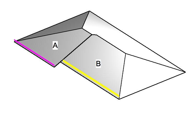
It seems I can't reproduce this very common roof structure and ask for your help. In the attached image, I want to make the plane of roof A be co-planar with roof surface B, as well as have that roof portion overhang a bit as shown. I understand it means that the bearing height of the wall shown with the purple line must be lower than the bearing height of the wall with the yellow line. However, when I try to reduce the bearing height of the purple wall, it will not allow me to fully lower it so that the planes are co-planar. It does allow me to lower the plane of roof A, but not enough to make it co-planar before I get an error message. I know that I can change the roof into generic solids and then make the change, but I don't want to do that, since I can't return it to being a roof object. Any help is appreciated ..... thanks
-
Ok .. thanks .... I'm just repeating the answer here so that I can find this thread in the future ... in case I forget again. The answer was to set the jamb to a class, and then hide that class.
-
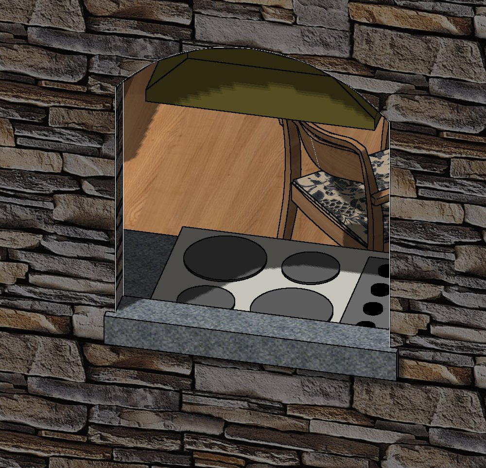
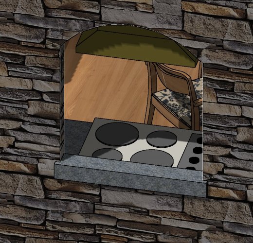
At one time I knew what caused white lines to appear around openings when inserted into a wall, but now I forgot and I can't fix this. I ask for help ... look at the attached image and tell me how to get rid of the white lines that appear around the opening on the corner edges of the opening/wall. It occurs in OpenGL and RW.
-
UPDATE: I discovered that I can insert a window dormer from the VW libraries ... IF.... I click and drag it directly on to the roof. Whenever I first drag it on the drawing (but not on the roof) and then I drag it over the roof (in top/plan view) then it does not insert itself as a dormer. This seems odd to me. Is it supposed to work that way ?
-
thanks ... but I tried that multiple times. Perhaps I should have asked the question this way .... When I drag my window symbol over the top of my roof, and the roof does not high-lite nor show any indication that it will insert it, then what have I done wrong ?
-
I'm embarrassed to ask this .... I want to make a roof dormer and the manual says to insert a window symbol, but NOT a plug-in object. I can't use the 'window' tool because that makes PIOs. Then I went to the libraries, and every library has a PIO for windows from various manufacturers. So ... how do I convert a Plug in object to a symbol so it can be inserted in a roof to make a dormer ? I tried to 'ungroup' it but that won't let it be inserted.
-
well ... thanks for the effort. I've been trying to figure it out, and this is my observation. The DTM model is set up by using perimeter 3D loci in the source data, all set to a certain elevation (let's say -2 ft) I'm not using imported survey data. These elevations are noted by me in the field without a survey. The 'hole' seems to be caused by two 3D loci that have an elevation lower than the perimeter loci (= -2 ft 3 inches). So, I guess I solved this by changing the perimeter boundary loci to be lower (- 3ft). But this puzzles me because I had my DTM settings set to minimum elevation much lower ( - 5 ft) so I should have been able to see everything without a 'hole' down to minus 4 ft --- right ? Perhaps ... is it possible that VW won't process negative elevations correctly ? In this case, I set up the finish floor to be = 0 for my convenience. PS: I've tried to find corrupted source data based on your comments, to no avail. I've had multiple freezes with this file whenever trying to render using 3D extruded contours, but can't figure out why. (It doesn't happen every time ... the worse kind of issue to solve.)
-
yes ... thanks for your reply .... I stripped down the original file and attached it. I've found that I can move the "hole", but can't get rid of it if I try to keep the same elevations. I attached a jpg image of the same 'hole' ... after I moved it. I know that i can eliminate it if I change the elevations in the DTM source data, but I don't want to change those as I'm trying to model actual conditions. NOTE: I am working in VW 2015. DTM test.vwx
-
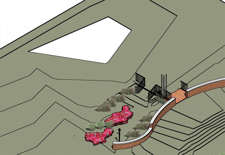
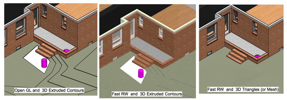
Can anyone explain what is wrong here ? The attached image shows an existing topographic DTM that has a depression next to the steps. When setting the DTM to show 3D extruded contours, there appears to be a hole in the DTM (next to the purple cylinder). Rendering with OpenGL or RW has the same result. However, the 3rd image shows the DTM with 3D Mesh or 3D triangles instead of extruded contours. I tried to reset the DTM settings to have a lower minimum elevation, but it didn't fit it. All images show only the existing DTM (not proposed) and the proposed layers are turned off. Any suggestions ?
-
can VW architect with RW use textures that can be downloaded from sites that share Sketchup textures ? If so, how do you change the file format so that it is useable in RW ? Please provide any tips on how to translate or use Sketchup textures. Thanks ...
-
thank you so much for helping out .... as usual, it was something I just didn't understand.
-
I'm puzzled .... if I put a texture bed in class 'A' on a DTM and then turn off the class 'A', it seems the DTM still shows the texture bed, even after updating. I was trying different options, so I want to have different texture beds on the DTM and easily be able to toggle between options. Is there a method to do this ? Am I just not seeing things correctly ?
-
Wes: thank you very much ... that was the simple solution I was looking for. It now shows up on the second floor 2D plan view. Sorry I didn't notice that little check box. I can't help but notice, however, that it isn't perfect. If I try to view the second floor only in a 3D isometric view with OpenGL, then the stairway does not appear. I guess it can't possibly work the way I hoped, because if I had both layers turned on, then I'd see a duplicate of the same stair ... unless it was smart enough to know that I only wanted to see one stairway in any view I designated. I need a software program that monitors my brain waves and acts accordingly. (well .. maybe not .. that might crash my computer)
-
I'm, embarrassed to ask this simple question ..... how do I get a single stair object to show up on both the first floor plan and the second floor plan ? If the stair is on the layer for the first floor, it won't show up on the second floor layer and vice versa. I could put two stairs, one for each layer, but that makes a mess of 3D views.
-
TomKen your reply makes me feel stupid that I didn't think of that. What a good solution ..... thanks.
-
UPDATE: thanks, but , it doesn't exactly work well. In a new sample file in VW2015, on a layer without a story, and an "unstyled" wall, I made a simple wall with manually inserted peaks. Then I ran the script. The first anomaly is that the suggested wall height is 253 ft high. Regardless of whether I adjust the 'final' wall height or not, these things occur: the peaks go away and the wall is a uniform height (as it should be) the bottom of the wall is no longer at 0 and I have to move it in 3D space in the Z dimension the OIP shows the wall height incorrectly. For instance, I set the wall height to 8 ft, and I can visually see it is 8 ft high, and the dimension shows it is 8 ft tall, but the OIP shows it with a height of 12 ft. I enter the correct height in the OIP and it might have several different outcomes: no affect; shows in correct height; adjusts the bottom and top to different elevations. I tried to figure out if these anomalies might have something to do with levels and story heights or layer wall heights, and I can not make any such correlation to correct the wall height using the stories/levels. It appears that once I use the command on a wall, the wall is forever corrupted to show incorrect values in the OIP Thus .... this script might still be useful if I get a wall with many peaks to remove, but otherwise, it has too many glitches for me to say it works correctly. But I do appreciate your help.
-
It works ... thanks .... but now I have to show my ignorance. I opened your file in VW 2015. A "custom palette" dialog box opened automatically. I made a wall with many peaks. Then I double clicked on the custom palette command, and it set all the peaks to the height I entered. Success. BUT ... in that file, I found the custom palette under the menu WINDOW>PALETTES>CUSTOM. I quit, then re-started VW2015. The command is longer there under the menu "WINDOW". So .. how do I load this new command into my copy of VW2015 ? I assume I have to load something into a library, but what ?
-
thanks ... but .... I could not find that command. I am using VW 2015, so is it possible they might have added that command in a newer version, but it is missing in VW 2015 ? Is there another way to do it ?
-
I used the command to "fit walls to objects" and the walls properly extend up to the next object (ROOF). HOWEVER, sometimes I make a mistake, and I want to "un-do" it. I find that I select the wall, but in the OIP there is no field to correct the extension. I adjust the 'top bound' to a ceiling or roof, but the wall retains the height it generated after I used "fit walls to objects". i can manually delete vertexes in the walls, but I still end up with a wall that is not the correct height for the top bound. So ... how do I "un-do" the "fit walls to objects" command ? (that is assuming I've made too many changes to use the 'un-do' command.)
-
Each case is different, and yours is different than mine. My problem was that VW2015 initially worked well on my 2009 MacBook Air. Then, I upgraded the MacOS and Safari and didn't realize until later that VW2015 would no longer initialize on the internet from my MacBook. My older version of VW 2014 still initializes on the internet so I can use that on my MacBook Air. I was (and am still) using VW2015 on my newer iMac with Yosemite (OS 10.10.5) but I can not upgrade the MacOS without also having to upgrade VW. Since I am retired, I don't intend to upgrade VW ... so I'll keep the same Mac OS and iMac until they are dead .... for the sole reason of keeping VW 2015 functional. I still think Nemetsheck is deficient for not making a patch for the internet initialization so I can use VW 2015. However, I doubt I'm the first to have software become outdated and I guess no software company cares about that. In my view, I paid for something and I can no longer use it . i think that is bad practice.
-
well .... it turns out the solution was to upgrade everything. Nemetsheck will not allow anyone to use it without internet activation. It seems when Apple upgraded their Mac OS, that caused a problem with the VW version activation. I suppose I could try to downgrade the Mac OS, but that simply causes the browser to be downgraded, which makes internet use inconsistent. So ... it is the same story we've all suffered with computers for years .... upgrade or die. In this case, I'm dead. (You are too .... :)
-
Dave: thanks for the help, but ..... I looked for "caustics" in those places you mentioned, without success. I opened the VW help manual and searched for 'caustics' and returned "no results". I suspect this feature is in a newer version, and not available in the version I'm using - VW 2015. Does that mean that I can not generate the light reflections that I want in VW 2015 ? (as mentioned in the original post). .... or is there another way to do it ?