


Mitchell (the other one)
-
Posts
87 -
Joined
-
Last visited
Content Type
Profiles
Forums
Events
Articles
Marionette
Store
Posts posted by Mitchell (the other one)
-
-
I do this a fair amount and use michael's first method:
- review the PDF to see if you can determine the scale,
- set your design layer scale to match,
- import the pdf
- use Modify > Scale Objects > Symmetric by Distance, then measure a known dimension on the PDF, then enter the known dimension,
- after the PDF scales, measure several other known dimensions to check the result, it is not unusual to have the horizontal dimensions correct but vertical are slightly off,
- if the dimensions are correct in one orientation, you could work out how much they are off in the other and use Asymmetric scaling to correct but that depends on the importance of the PDF to the project,
- once the scaled PDF is where you want it, change the scale of the design layer.
-
This might be a better question in the Buying and Selling Vectorworks Licenses forum. Scroll down 8 headings to find it. And congratulations on retiring to Salt Spring Island - great choice.

-
23 hours ago, Boh said:
Be aware tho that if a class is set to invisible in the workspace it may be visible in vp annotations but you can’t edit annotation objects in that class until they are set to visible in the workspace also.
Now there is a semi amusing feature that would have had me guessing for a while - thank you for the tip.
-
What about creating a new class, "wall - temporary", put the wall in that class and then turn it on and off as needed. When done, move the wall back into the same class as the other walls?
-
This is a good thread to start with . . . .
And I agree with Pat's "far superior" rating.
-
I'll second the WYSIWYG approach. As I work on a drawing I want to be looking at what the final result is going to be. I find changing the scale of a viewport at the last minute results in much muttering at the screen as some text moves over something I'm trying to show.
-
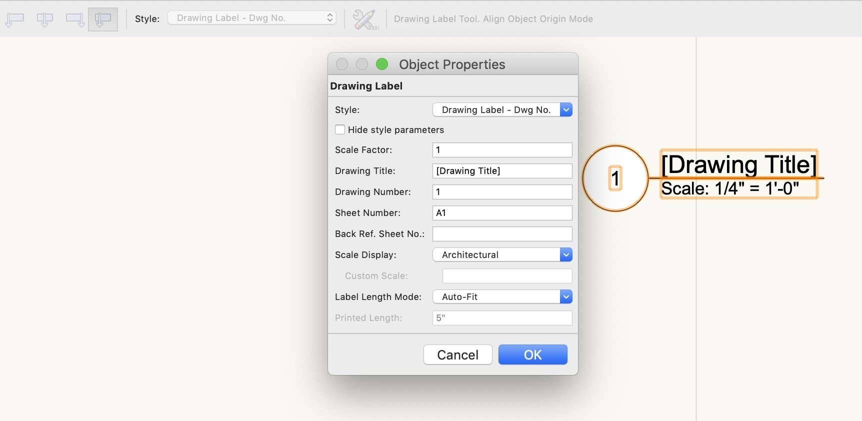
Ok that worked, thank you . . . . I would not have found that easily. I like the use of the drawing label style, set it up once and then it is always the way you want . . . but the configuring of the style itself seems to be still in programmer mode rather than user mode.
-
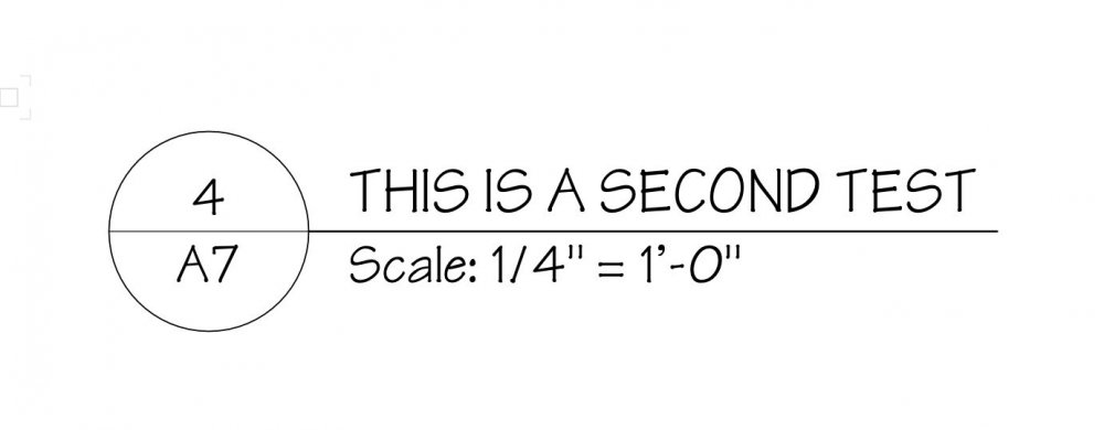
A follow up question as I update my template to use Drawing Label styles. I can edit each style setting font and text size, however I can't seem to find the setting to get the word "Scale" to be all caps. I have selected the text in the Edit Drawings Label Layout and then set the font, size and the upper case - it still shows as capitalized lower case. In earlier versions there was an option to select capitalized or all caps. Can anyone point me towards the setting to control this in the drawing label style?
-
 1
1
-
-
Thank you, that pointed me in the right direction. I had clicked Style > Replace earlier but had not drilled down to find the Drawing Label file in the Vectorworks Libraries.
-
19 minutes ago, markdd said:
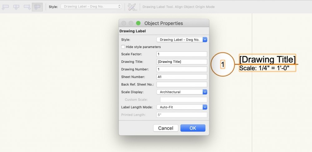
I'm assuming you are referring to the new Drawing Label Tool. If you can choose which style to add to the drawing using the pull-down menu in the mode bar. You can also edit, create and style any label to suit your needs now using the plug-in styles functions.
That was my thinking as well, however Drawing and Sheet don't seem to be an option. I could duplicate the style and create a drawing and number style . . . but this was already a option in previous versions. Why do I suspect one of the gurus will let me know it its now part of some automation and once configured all will be amazing?
-
My Friday is feeling like a Monday . . . . VW 2021, when I create a drawing label its number style is drawing only. How do I change this to drawing and sheet?
-
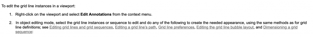
And in answer to my question, a little reading of the online manual and while gridlines should be placed on a design layer, they can be edited (to a degree) through Viewport Annotation.
-
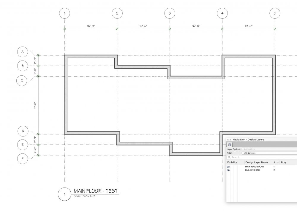
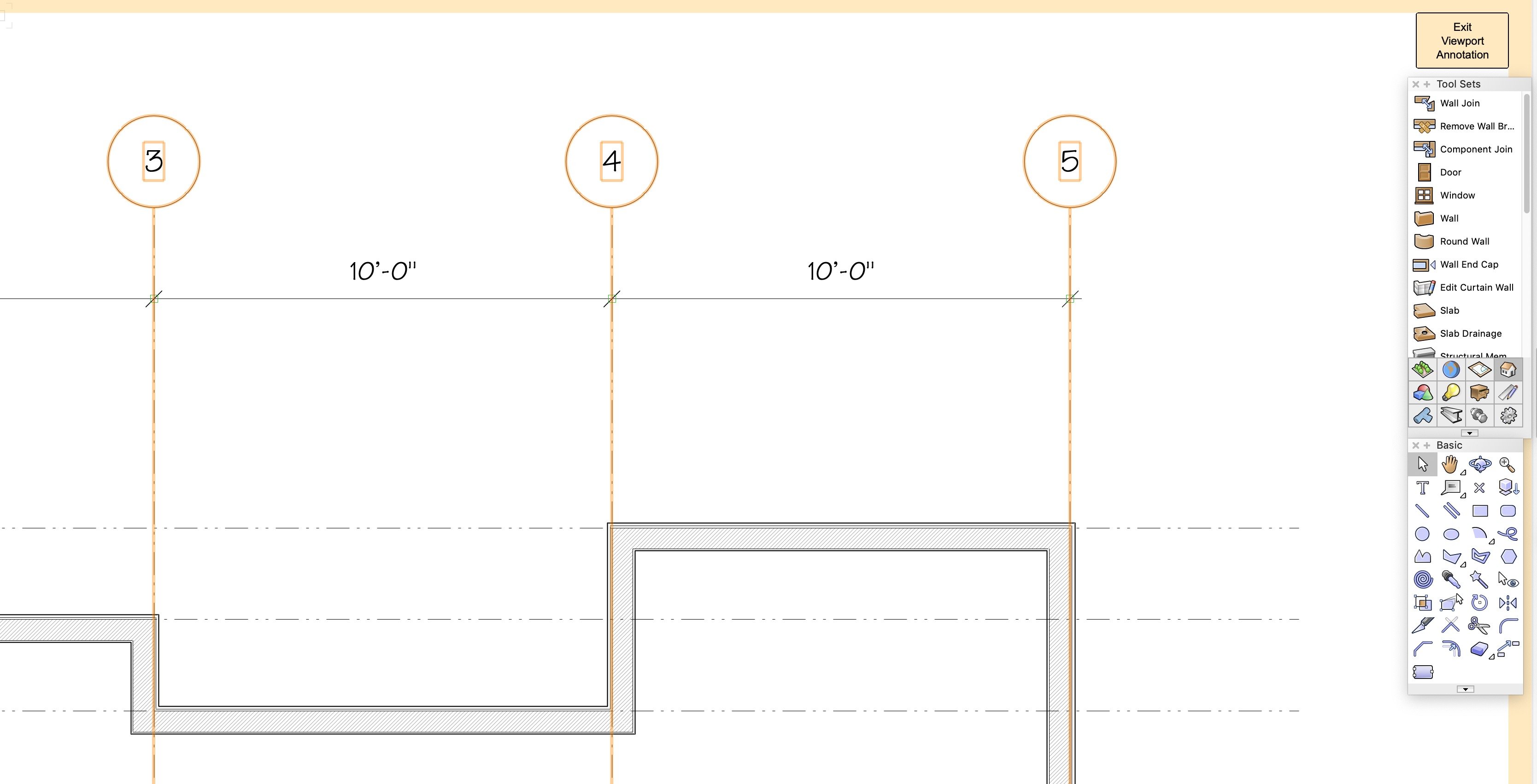
I'm not sure if this is part of the new Grid Line Tool behaviour or not. First attached image - I have created a sheet with two layers, Main Floor Plan and Building Grid. Second image, I have doubled clicked to enter Edit Viewport, then choose Annotations expecting to add a note below the drawing title. When I click on the grid lines / bubble their settings (shoulder, bubble scale etc.) can be edited as an annotation. As a possible feature, I'm trying to think of how this helps with workflow.

-
9 hours ago, bentonboyd said:
@Wes Gardner thanks for the reply. When I started the project, I assumed that I would be cutting the tail/gables off, but unfortunately the end of the truss, including joining plate, extends past the wall. So I should have said that it is raised heel with truss extended past the exterior wall (including both the top and bottom chords). Think I'm stuck building the wall up around them.
We have revised trusses within an existing roof on several projects but only under the guidance of a structural engineer who understands wood. (despite the presence of an iron ring, not all do) From your description I believe we have made a similar change where we inserted blocking (and a number of somewhat expensive Simpson screws) between the top and bottom chord inline with the bearing wall and then were able to remove the overhang. Some photos of the truss, a sketch or two and a consultation with a good structural engineer should answer your questions.
-
11 hours ago, Joe-SA said:
We recently did a series of log houses constructed with half-logs hung on a standard 2x8 stud wall. We put a log texture on the face of a 5" thick exterior component. We had to offset the side elevation texture to account for the lapping of the logs as they turned the corners. Custom corner log symbols showed the full round ends of the logs while other elements like log brackets and fully modeled gable log trusses assisted in hiding the lack of depth in the wall texture.
If you don't mind sharing a few images, I'd love to see how this turned out.
-
38 minutes ago, Matt Panzer said:
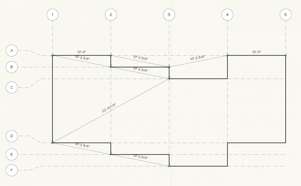
The dimensions being placed at the start/end points are by design. The objects should be placed with that in mind (the start/ends should not be at the actual model geometry). The shoulder control point reshape behavior was also implemented to address a variety of cases without adding too much complexity. However, we can look into ways to improve this in the future. Also keep in mind that you can select multiple Grid Lines and reshape them or their shoulders at the same time.
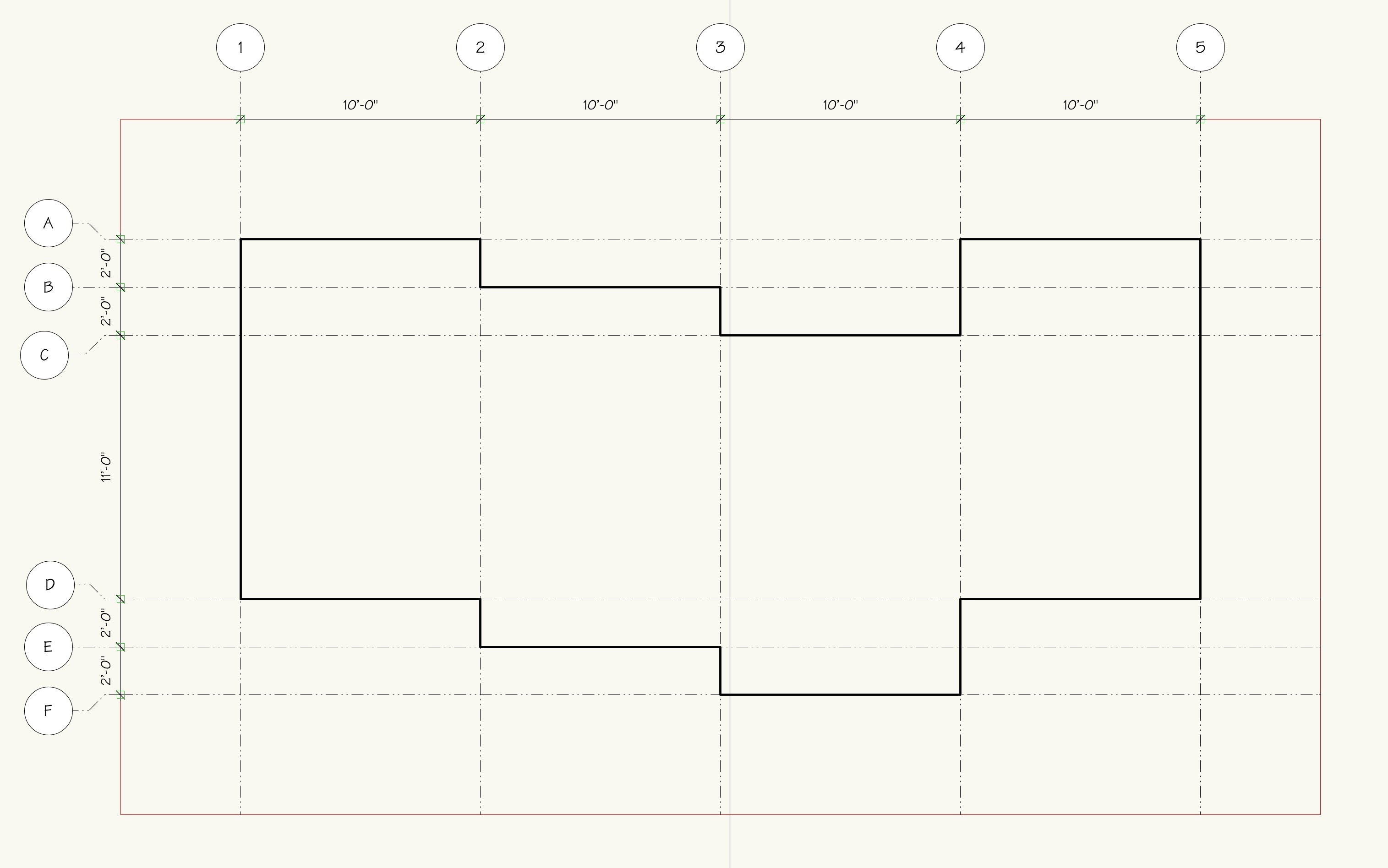
Thanks - just figuring out what might be the best workflow for the grid lines. Rather than adjusting a number of vertex points I created a temporary rectangle and then aligned the grid lines with each corner (thank you smart cursor) on the temporary rectangle. All grid bubbles, dimensions and shoulder elbows now align. The OCD in me is now content.
-
3
-
-
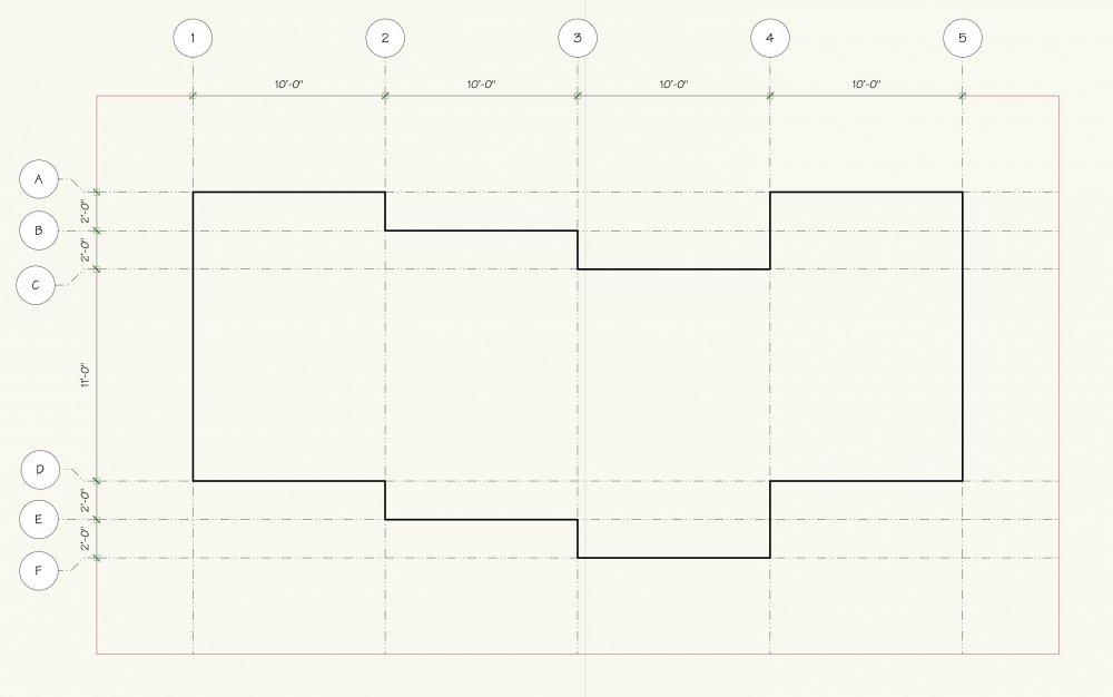
I have been trying out the new grid line tool and really like it. I have a question about how it is meant to be placed. In the attached image I placed the grid line at the corners of the shape. Then dragged the bubbles to align. Then using Dimension Grid Sequence I get the attached result. The dimensions are placed at the start point for each grid line rather than an offset from the bubble itself. Also, the Add Elbow to Shoulder(s) seems to work from the start point and dividing the shoulder into equal thirds. In my drawings this feature (which I really love!) would be better working a fixed distance from the grid bubble. I can get them to align however the dragging and aligning of the vertex points starts to take away from the "this is cool" quality of the tool.
-
Perhaps VW 2021 arrives on October 06 . . . . .

-
Perhaps the previous teasers covered all of the new features in 2021.
-
 1
1
-
-
Well, there is a "duh" moment for me. I'm
stealingborrowing that technique. And adding another beer to the total that I owe Wes. -
Ahhh, hadn't thought of the mirror tool. But alas, no joy . . . . . . . . I also tried grouping the floor plan before mirroring, same issue with the wall joins coming apart.
-
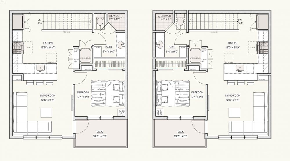
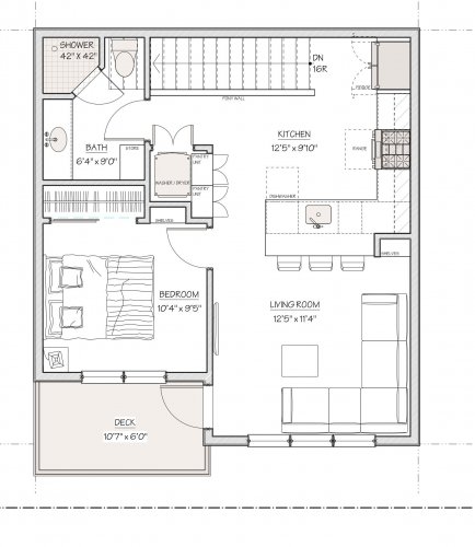
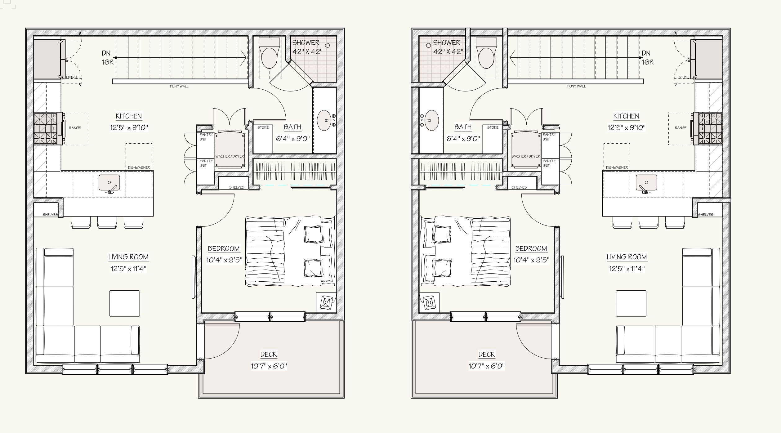
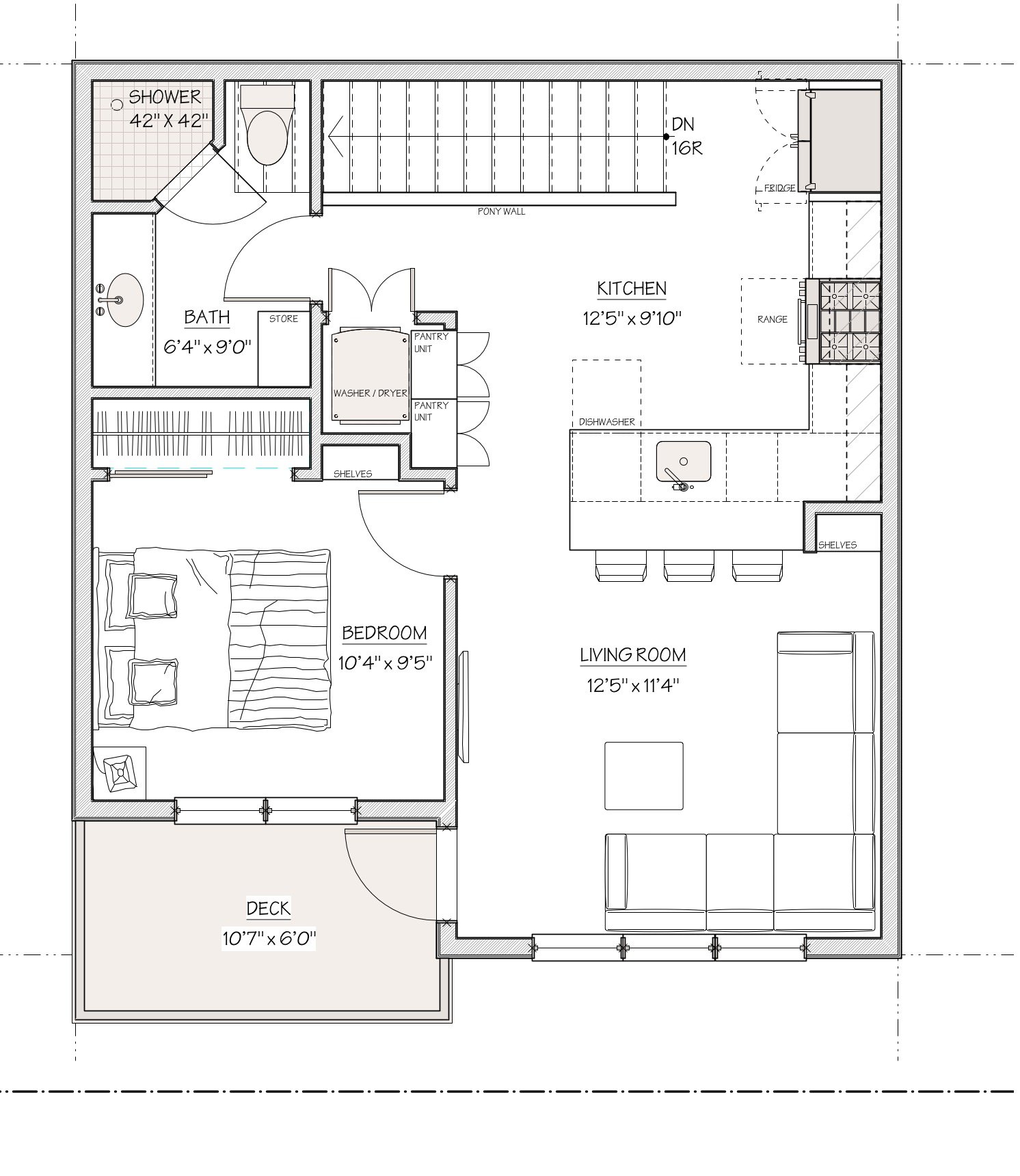
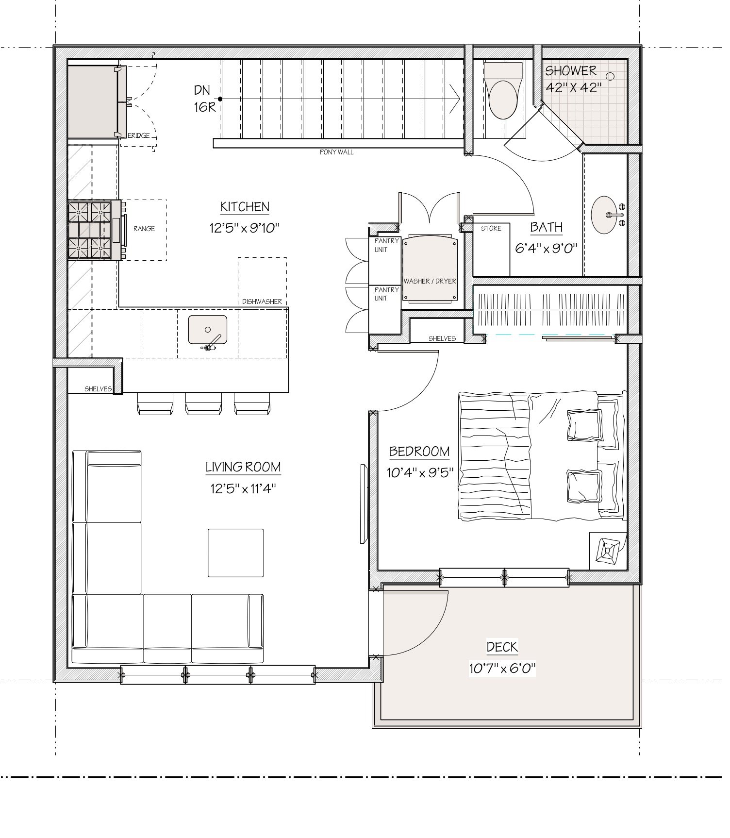
With some time on my hands I'm moving from VW2019 to VW2020. It has been a mixed experience. The first image attached is a floor plan I'm working on. The second image is the same floor plan flipped horizontally. And now all the horizontal walls have broken their joins and extended the depth of the wall they were attached to,. Both plans are in the same file, I duplicated the layer so I would have an original and a flipped layer. I drew a marquee around the plan, then Modify > Rotate > Flip Horizontal. And then the result you see in the second image. Any explanations / guidance would be appreciated. It only takes a few minutes to repair the walls . . . . . but I shouldn't have too. And now I'm calling it a day and going for a beer.
Upper suite original.pdf Upper suite flipped.pdf

-
There are those that say VW2020 Architect also does not have a stair tool. (smile)
-
1
-
2
-
-
Once you have created the Door Style you want and then applied it to the door PIO, is there any advantage to then converting that 'styled' door PIO to a symbol? The conversion to a symbol seems to loose some of the functionality of the style, Use Wall Depth for example. I'm just having a little problem letting go of years of placing door symbols from my master file of doors.


Help with the property line tool.
in Architecture
Posted
'very cumbersome' is a polite way to put it. I have given up on this tool having never had a successful result from it. I use the line by line method noted earlier and cringe a little when I get a site plan with several arcs.