


mike m oz
-
Posts
4,885 -
Joined
-
Last visited
Content Type
Profiles
Forums
Events
Articles
Marionette
Store
Posts posted by mike m oz
-
-
Hardscapes work differently to slabs:
- they can be 2D only or 2D + 3D
- When the 3D is activated there are separate thickness parameters for the body and the border.
- They don't have a Z value. Instead they have an Elevation value which is relative to the Z of the Design Layer they are in.
The Elevation value is always to the bottom surface of the Hardscape object so to get the top surface at a required level you have to set the elevation value to the required value for the top surface minus the thickness. Hence the wish by DanH.
-
 1
1
-
-
Slabs have an option for the datum to be Top of component or Bottom of Component. With Hardscapes the datum is always the bottom of the object. Hence your problem with it no longer being possible to enter negative values.
You should submit a Wishlist request for Hardscapes to have an option to have the datum at the top or bottom of the Hardscape.
Where it gets tricky is if the border thickness is different to the body thickness because both have their height set from the bottom so one of these would need to take precedence. Probably the body.
-
1
-
-
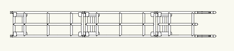
Rotate the truss elements first and then create an Auto Hybrid of that. It would be better to do all four truss elements together so you have a correct view of the total truss unit.
-
Alan, VR is the future and Vectorworks will need to get better at it.
The biggest issues for us as architects will be getting clients to pay for the work that is required to produce VR of good quality and having computers with the grunt required to render them in a reasonable timeframe.
Personally I would prefer to not have to do that by exporting to another program where once changes are made the model has to be reimported and the texturing and lighting work has to be redone. I've been there and done that and it is a time consuming pain in the butt.
-
Export WebView gives reasonable results as long as the model is not overly complex.
-
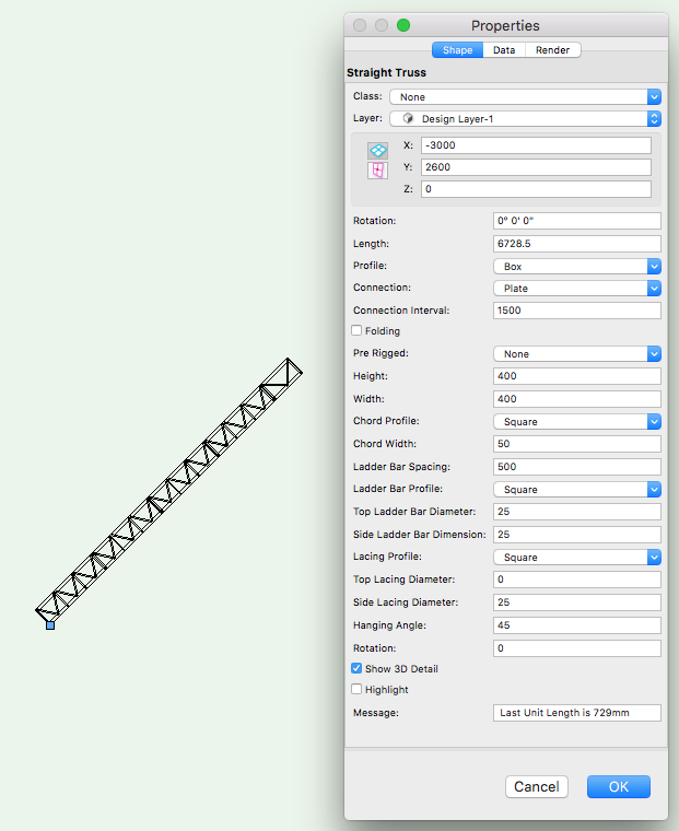
You can incline a Straight Truss by changing the Hanging Angle (near the bottom on the OIP). Immediately below that is a field for Rotation which allows you to rotate the truss around its longitudinal axis.
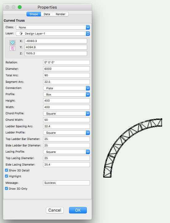
With a Curved Truss you have to checkmark the option Draw 3D Only (near the bottom on the OIP).
-
Post a file with that door in it so it can be looked at.
-
Tool mode shortcuts:
- the U key toggles through the first group of modes
- the I key toggle you through the second set of modes
- the o key toggles through the third set of modes
- the P key opens the tool Preferences.
-
1
-
-
This should fix it permanently:
- Open a document using the Default template.
- Change the units to metric (file/Document Settings/Units...).
- Make whatever other changes you want to be your basic (Page setup, Design Layer Scale, default text font + size, etc.).
- Save As Template with the name Default.sta (this will save into your User Folder - don't save it to another location).
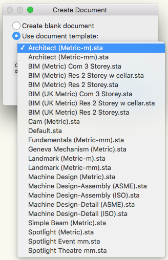
- Start a new document using File/New... Choose Default.sta from the template list.
From this point on every document you open will be as per that Default.sta template until you make another selection in the New Document dialog box. From that point on whatever you selected last will be what is used until you change it again.
-
Whatever the last selection in the dialog box was will be what you will get from that point on. It is also possible that if you crashed it may have reverted to the Create blank document option.
Try opening a new document and choosing from the list.
Other questions:
- Did this problem start after a Service Pack upgrade?
- Are you in an office situation where someone else may have inadvertently redefined the Default template you use?
-
This happens if you select a Blank File or a Template File that has its units set to Imperial.
With each new version the first thing I do is create a new Default template that has the page size, units and text size that I most use. I then set that to be my usual New Document choice.
-
You would have to exchange information through IFC or 3D DWG. The risk always is what information doesn't get translated correctly.
If you have to collaborate then the best solution would be to split the project up between you so you are doing discrete work that doesn't require continuous file translation.
-
Alan just change the Wall drawing mode to Right Control Line Mode.
-
1
-
-
Try selecting a Door object and on the Render tab of the OIP make sure the Texture pop-up is set to Class Texture.
Then on the Attributes Palette apply Make All Attributes by Class (downward arrow at the bottom activates the pop-up).
-
Is there a reason your using referencing rather than Project Sharing?
-
The webinars are a good place to get more detailed information. http://www.vectorworks.net/inspiration/industry-webinars
Here are a couple of longer videos on Landmark which go into more detail:
- https://www.youtube.com/watch?v=W89T7eZ_Kso
- https://www.youtube.com/watch?v=WUYYqg2vVkM
-
nca77, if you set out what the workflows are that you need help with you will probably get help from the user base here.
If you want Vectorworks to change so it works exactly like Autocad then it isn't going to happen. If you expect Vectorworks Landmark to have the capability of programs like Civilcad at a fraction of the price then you are also likely to be disappointed.
-
If you have Service Select there are topic specific resources. There are also many You Tube movies by Vectorworks and others.
-
Landmark Learning Resources:
- Vectorworks website: training guides, webinars and courses.
- You Tube: Many Landmark videos by Vectorworks and others.
- Third party books on Landmark by Jonathan Pickup of Archoncad and Tamsin Slatter. Both provide training as well.
-
No, that is not possible.
-
In your User Folder there is a Libraries folder. Within that there is a Defaults folder containing a folder named Door - Custom Leaves.
Save a file with a unique name that has your custom door leaf symbol in it. Then place that file in that folder called Door - Custom Leaves.
You can access your User Folder from the User Folders tab of Vectorworks Preferences.
-
2
-
-
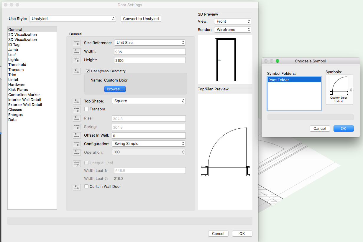
Once you have a Door Hybrid Symbol you can either use it as a symbol inserted into a wall or you can use it within the Door object by selecting the Use Symbol Geometry option.

-
RamiahL you need to make your own Hybrid Symbol for that door:
- Model the door in 3D using unique Classes to control the graphic appearance of the components.
- In Top/Plan view draw the required 2D appearance in Screen Plane objects on top of the 3D, once again using unique Classes to control the graphic appearance of the parts.
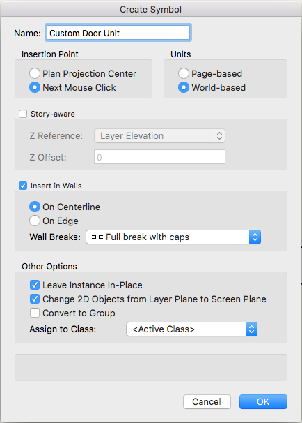
- Select both the 2D and the 3D and create a Symbol of them by choosing Create Symbol on the Modify menu. (use the settings in the image below.
- The bullseye target marker that comes up will make the insertion point where you next click so choose carefully so that the frame is where you want it relative to the centreline of the wall. I would make it the midpoint between the left frame extremity and the right frame extremity so if you use Flip on the OIP the symbol doesn't move in the wall.
-
Do you have Unified View turned on? (The icon just to the left of the View pop-up on the View Bar).
Fillet This?
in Troubleshooting
Posted
Round all the edges using the Fillet tool and then use Add Solid to add back in the timber that would not have been removed where the cross pieces intersect with the rails.