


mike m oz
-
Posts
4,880 -
Joined
-
Last visited
Content Type
Profiles
Forums
Events
Articles
Marionette
Store
Posts posted by mike m oz
-
-
10+ years back our state Archicad distributor produced a tool like this that would automatically adjust to height changes and it had an option to display the result in brick coursing (with the brick coursing height being user definable). At the time I recall being envious and wishing that Vw was that nimble.
-
 1
1
-
-
I came across it afterwards and voted for it.
You should post a link to it in this topic to make it easy for others to find it and vote for it.
-
kyo_ny that needs to be a separate tool. You should Wish List it.
There used to be a Vectorbits tool like that but it is no longer on their website. You can create your own using a symbol and a record. The file below has a Page Based Symbol with an attached Record to give you what you want. You enter the Height through the Data Tab of the OIP. The symbol is page based so it is the same visual size on layers irrespective of scale. If you need to edit the symbol do it while you are in a 1:1 scale Layer (a Sheet Layer for example) so you can use real size units and text pts.
Jim, there are several variations that need to be added to the Elevation Benchmark tool. You should also wish list that .
-
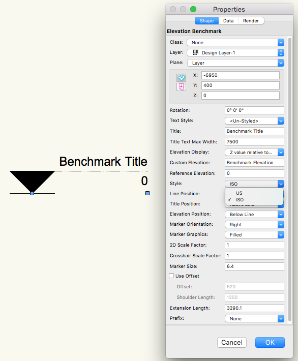
The Elevation Benchmark tool has a US mode and an ISO mode (see the image below for the latter). There are also controls for the arrow orientation and where the level and text are located
Some more marker modes would be useful though.
-
I think Vw needs to cover all BIM requirements by having a structural version and a services version.
-
2
-
-
Christian, the Stair tool should be able to do your stair.
It is not an unusual configuration and you should Wishlist for the Stair tool to do that form and for it to be added as a standard configuration.
-
1
-
-
Quote
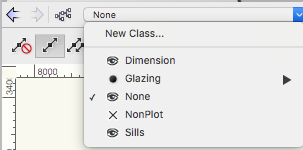
I've set the NonPlot to "not visible" but they didn't go away.
Do you still see them when you make None the active class?
-
These are 2D loci which control where the wall gets cut in Plan View. They are in the NonPlot Class and if you can see them that is either the active Class or you have that Class visible.
The NonPlot Class should always be set to not visible. It is the Class that is used for drawing elements that are not meant to be seen.
-
There are couple of terracotta roof tile hatches in the hatch drawing by Katerina Panagiotakis posted at Vector Depot.
-
2
-
-
Are you a long way from the internal origin?
Before you reinstall Vectorworks try resetting the Preferences. Button in bottom LH corner of the Vectorworks Preferences dialog box.
-
I don't think it is documented Kevin. I worked it out from my own experiments after I discovered that a portion of reshaped wall that was above the cut plane was showing as being cut by the Cut Plane.
Walls and Wall parts that are above the Cut Plane should show dotted. The fact that they don't is unfortunate.
I suspect that the different behaviour by Curtain Walls is because their cut view is generated by the auto hybrid capability.
-
3
-
-
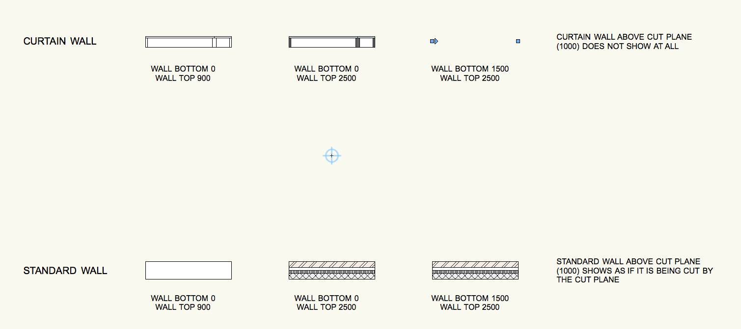
Cut Plane only hides the components of standard walls that are below the Cut Plane. Standard walls that are entirely above the Cut Plane still show as if they are being cut by the Cut Plane.
Cut Plane shows the top of curtain walls that are below the Cut Plane. Curtain walls that are entirely above the Cut Plane do not show at all.
You should Wish List the changes that you would like to see to this behaviour.

-
2
-
-
Have you tried quitting Vectorworks and restarting your computer?
Does the file have lots of hatching or lots of imported images in it?
Does the file have imported PDFs in it?
-
-
Menu Tools / Workspaces then choose from the list.
-
Fundamentals doesn't have Section Viewports so if you are using the Fundamentals Workspace you won't see that command in the View menu. If you switch to the Spotlight Workspace it will be in the View menu.
If you have an Industry series version (Architect, Landmark, Spotlight and Designer) you can add it to the View menu in the Fundamentals Workspace by editing the Workspace.
-
This is a great improvement and one that people will really enjoy using. Being able to see what is happening in multiple ways as you work will add to the experience and save time.
-
Steven, I can't work out why. Submit it as a bug.
-
Totally agree.
Many metric users have to use the Custom Display option instead, thus losing the automatic aspect of the object. For example we use Drawing Units set to mm but have to express levels in metres.
-
2
-
-
No there isn't.
Post a request for this enhancement in the WishList section.
-
Totally agree.
Our protocol is for the drawing units to be mm but contours need to be in metres. We also need an option to have the unit mark show, preferably with a space between the numeral and the m mark.
-
Pat's solution would be the best way to go with more complex routing.
-
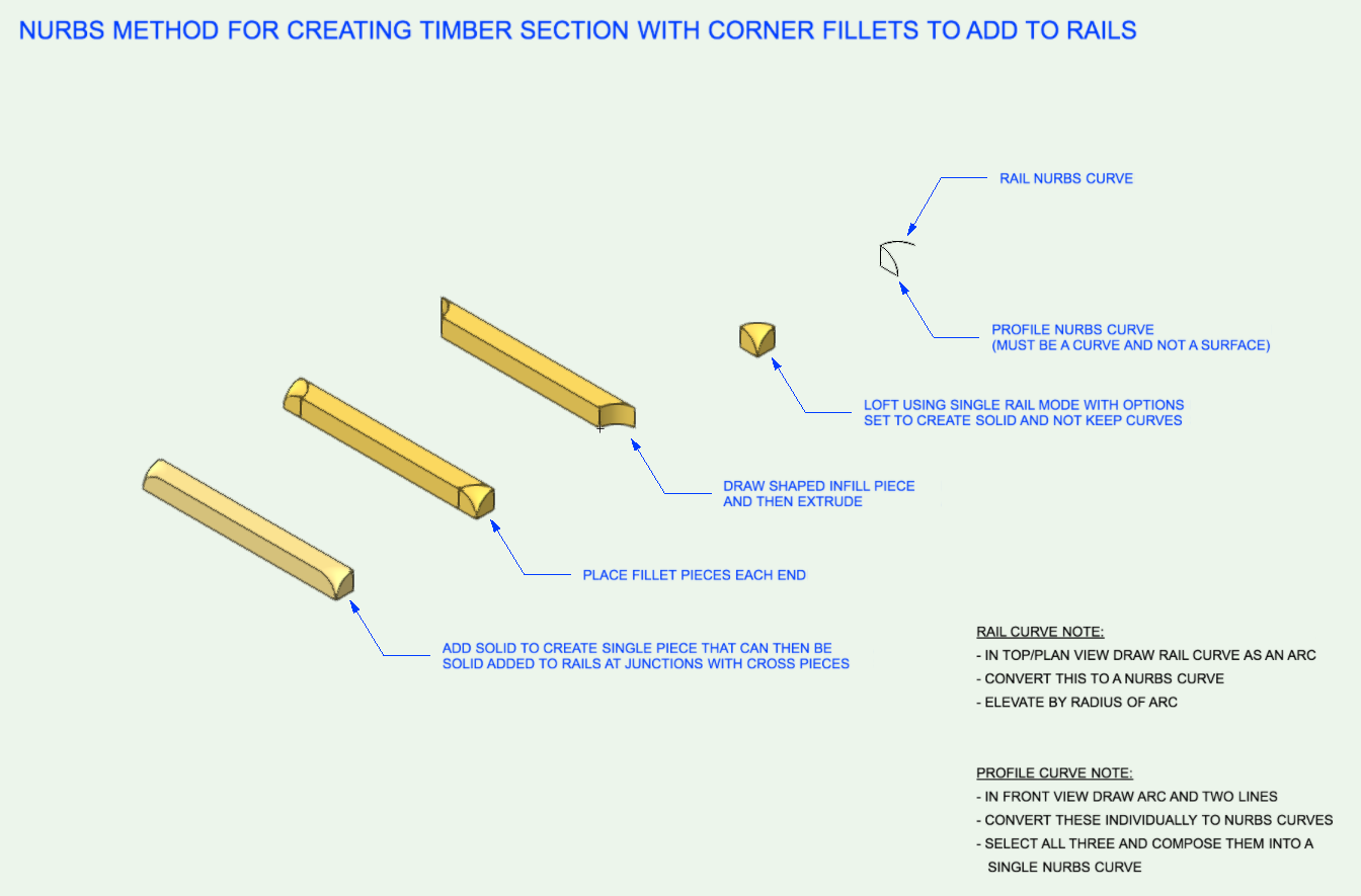
Another way to do it using Nurbs. You could build up a 'Blue' Symbol library of these for different radii (Blue Symbols convert to a Group on insertion).
This corner fillet object is 1/2". You could create the other corner fillet objects by duplicating it and then using Scale object to change its size. Once you have your required range of corner fillet objects create Blue Symbols of them by choosing the Insertion option to Convert to Group.
-
1
-
-
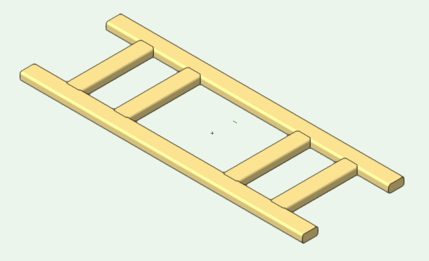
A better way to do it:
- model the rails and round the edges
- model a cross pieces 1'" longer than is required.
- model a piece to subtract from each end and round two of its edges.
- Solid Subtract these two pieces from the rail.
- duplicate for the other rails.
See attached Vw 2017 file.
Issue w Visibility - Missing "Eye" Icon?
in Troubleshooting
Posted
Try what markdd has suggested because you should be able select the visibility you want by clicking in one of the three columns. From left to right these are visible, invisible and greyed.