

lisagravy
-
Posts
203 -
Joined
-
Last visited
Content Type
Profiles
Forums
Events
Articles
Marionette
Store
Everything posted by lisagravy
-
-
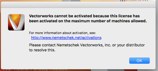
Hi there I tried to swap my vectorworks serial number with a colleague's, as I'm running fundamentals and my colleague runs landmark. As my colleague is on holiday for a few weeks, I thought I could just swap the serial numbers over to allow me to use the landmark features on my own machine over this period. I swapped the serial number successfully by removing my own serial number, adding my colleague's, and restarting vectorworks, but on activation of my colleague's serial number I have the error message below, stating that Vectorworks can't be activated due to being on too many machines. I understand the reason for this, but my problem is now I can't revert to my previous serial number - as I can't open Vectorworks, to get to the serial number options to change it back! Vectorworks won't open without activation, which I can't do. Does anyone have any ideas? Can I assign my old serial number prior to opening Vectorworks so that it can activate properly again? I now can't open Vectorworks at all on my own machine. Any advice much appreciated.
-
Hi, I have landscape areas on my site model I'd like to be visible on my sections, but when I create section viewport I only get a 3D profile of my site model. I'm not concerned about the display of the plants, but I need an indication of where they are on the section, even as a line marker. Any ideas much appreciated. Lisa
-
Seconded!!!!
-
Thanks, that's really annoying and quite a basic functionality! I've found a workaround in that I can copy in the plan I originally worked from (at 0 height) into the model, manually move each item back to zero, and create a symbol from each solid, selecting insertion point by click and clicking on a point on the ground plane. This means each item is a symbol with Z height 0 on the ground plane, and I can adjust each Z height to whatever I wish. Just quite a laborious process! I'll know for next time.
-
Hi, I have a significant number of 3d objects I have created through extrusions / additions / subtractions, all created to sit on Z height of 0. I then moved all the objects individually to various Z heights using the Move3D tool - however, I now want to adjust the Z heights, and I can't remember what I set each of the original heights to be. As such, I want to be able to type in the new absolute Z height without worrying about the existing height - but the Move3D tool seems to be set up for relative distance to current position, rather than position in relation to the origin. Is there a way I can change this, or another simple way to edit the Z heights? There is not a Z height option in the properties box, presumably because the objects have all been added / subtracted.
-
It's even more frustrating to know I'm doing it correctly and it's still not working! Thanks for your help. re: your issue... the converse of your advice would be to make sure your 2d display is set to existing + proposed, I'm assuming you've checked that?
-
Thanks for your reply - I've checked and the 3d display of my site model is already set to Proposed Only. (3d mesh solid? Is this ok?) I've tried clicking update and I still can't see my landscape areas in 3d. Good to know I don't need send to surface for future!
-
Hi there, I have created a site model in Landmark / Renderworks, and created a series of polygons which I converted to 'Landscape Areas' set to render as texture beds, and sent to surface. I can see these clearly in top / plan view, but in any flyover or render view I they disappear - even in final renderworks render settings! Can anyone help me with what I'm missing? Thanks, Lisa
-
Thank you! I think this is really useful in terms of consultation events etc, but the technical visualisation requirements for planning for wind farm developments have pretty stringent requirements in terms of visual projection - I'm pretty sure I could model a turbine and set them on a site model, but in terms of visual output to line up on top a photo which can be verified to within 1 degree of accuracy.... I'm not sure. I will need to have a look at the mathematics of how camera match works. I think my main problem is that I need to be able to differentiate between cylindrical projection perspective of a 3D view and planar perspective of a 3D view in terms of camera settings, and all the options I can see in Vectorworks are variations of 'perspective' rather than getting to this level of specifics, which would be required for these.
-
Does this exist? I've tried looking for (and indeed googling!) a ZVI function in Landmark but can't seem to locate it... (though appreciate this is an old post and functionality may have been removed?)
-
...
-
We use Vectorworks quite heavily in the office for 2D drawing, but are just really starting to get to grips with Landmark / Renderworks, and while I am loving it so far I'm not quite sure of the full extent of it's capabilities. I am looking to do some visualisations for a wind farm planning application, for which the levels of accuracy required by technical guidance for visualisation (published by SNH) is quite precise, and I'm not sure if it's something that can be achieved in Vectorworks or if I need to look at bespoke wind energy software (such as Resoft Windfarm / WindPro etc.) I need to be able to match a wireframe view of OS terrain information (for an area of up to 80km of Terrain50 contour shapefiles or DTM grid) with a panorama photograph, to an exact bearing direction and field of view. The wireframe needs to match the cylindrical projection of the panorama photograph (- i.e. NOT be in standard equirectangular / planar perspective as per a single standard photograph,) and the model will also need to account for the curvature of the earth and atmospheric refraction. My current feeling is this is beyond the realms of Vectorworks capability at present, (much as I would love this not to be the case!!) but I would appreciate the thoughts of users with more experience and expertise!!
-
Thank you!! This is perfect. I have a lot more to do, but I can at least understand where I was going wrong with this and apply to the others.
-
Thanks guys - I'm still struggling though?! Trying with a NURBS curve path and a 2D polygon, and still getting an error. I've attached the objects I'm using for reference incase I'm missing anything obvious?! Lisa test.vwx
-
Thanks for your reply, but unfortunately I can't get either of those options to work? All the instructions I had seen have said to use an NURBS curve as the path, so I thought that might be it, but I've tried both as 3D polys too now and the same error message occurs. And the Loft tool with both objects as NURBS is giving me an error mesage too?!! Argh. Is there a more straightforward way than this to make a hedge that follows the terrain? It seems like a fairly basic requirement?!
-
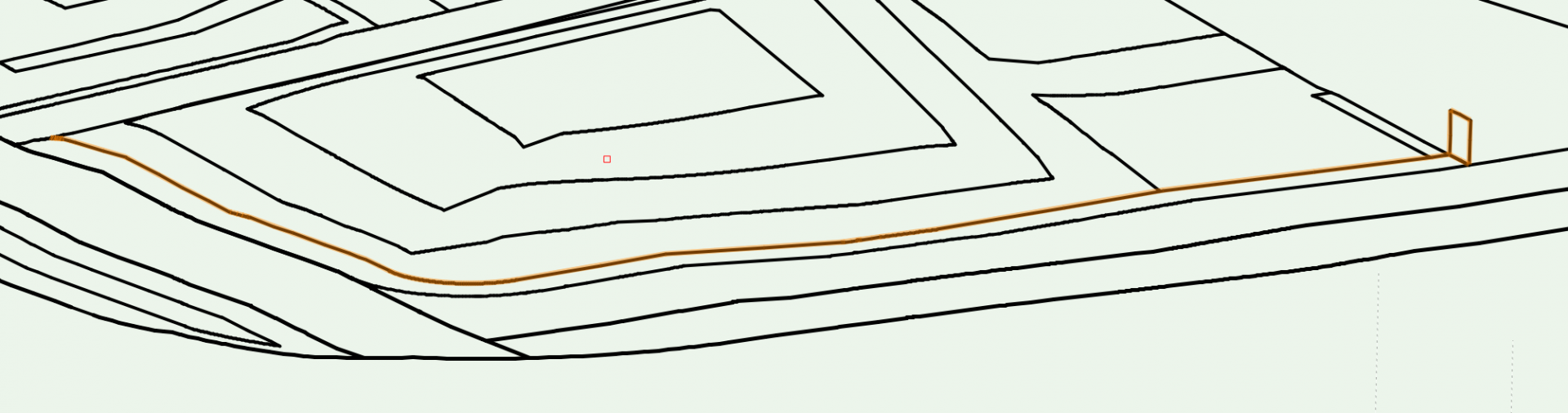
I am new to Landmark, and am having issues with the 'Extrude along Path' tool. I am trying to run an extruded box along an undulating ground line (to form a simple hedge following topography). I have drawn an NURBS curve path which varies in Z height (it is sent to the surface of a site model which varies in height, and then converted from 3D poly to NURBS curve). I then created a 3D polygon rectangle (as a section of the hedge) at one corner of the NURBS curve path, and selected both objects before trying to extrude along path. The NURBS curve highlights correctly as the path object and the polygon highlights correctly as the object to extrude, but I get an invalid path or profile object error message. Am I missing something straightforward in terms of how this tool works, or is there a better way of doing this? Thanks, Lisa
-
Yeah, I've tried hitting "Save" - it does open a save dialogue box unfortunately! I think Jim is right, it appears to be as a result of OS Sierra - colleagues running VW 2014 are having the same problem, while others with the 2015 version (albeit running as 2014) do not. It seems to be an intermittent issue - sometimes it works and sometimes it doesn't!
-
Yeah I thought that may be the case, but we have other Macs in the office also running OS Sierra and Vectorworks 2014 and they're all printing fine.
-
Thanks for your reply - the 'Darth' printer is actually the name of our office plotter - it's linked to our server, and all other machines can print to this machine from Vectorworks fine? I could print to Darth fine too prior to being off last week - the only thing I've done differently today is updated my OS to Sierra! Now regardless of the printer I select the only option I get is to 'Save' rather than print.
-
I am having the same problem - I assume I have somehow enabled a 'print to file' type setting, but I can't for the life of me see where this might be - can anyone help? (I'm using Vectorworks 2014 on OS Sierra.) Attached my File > Print dialogue box if this is useful - any pointers much appreciated!!

-
I'm currently trialling CameraMatch (2013/2014) with Vectorworks 2014, and following through the instructions for my first viewpoint - wondered if someone might be able to help me with an issue I am having. In context, the view I am trying to align is of a housing development, rather than just one house, and as such is nowhere near as close in range as any of the examples I have seen using this plugin, so it may just be the wrong thing to use, advice is welcome. I have modelled my development in Vectorworks in 3D, and set all the buildings to the appropriate positions and Z heights in relation to site levels. I have a photo I want to align it with, and also some reference points in the image. I also have a viewpoint position, i.e. where I took the photo, and a level height for this location. I have imported my image using cameramatch and set up the control lines and reference object in Vectorworks, but my model is way off when I set view to match, i.e. only a small percentage of it is even appearing over the photo and when I investigate it appears that I am way beneath my model. I wondered if there's a way I can set the viewpoint position / viewer height in the plugin to possibly remedy this? I had used Set 3D View to set the viewport and did set a viewpoint position / height there, but setting the view to match in the plugin appears to be overriding this to such an extent that it looks like I'm standing way below ground at the opposite end of the development. Any advice greatly appreciated! Lisa