


SBarrettWalker
-
Posts
335 -
Joined
-
Last visited
Content Type
Profiles
Forums
Events
Articles
Marionette
Store
Posts posted by SBarrettWalker
-
-
If you are using Vectorworks 2018, then I believe the menu command you are looking at is IFC Data Mapping. What you are seeing with "[Object.VW_Name] ELSE [Object.IDPrefix] + [Object.IDLabel] + [Object.IDSuffix] ELSE 'Window' " is the Field Value that is generated from pulling information from the Window object itself. With the Get IFC Property Node, you need to input the Field Name in order to get the Field Value. I believe in your example, the Field Name is Reference or IFCReference or something along those lines. When you input that into the node, the output will be the string value for this formula: "[Object.VW_Name] ELSE [Object.IDPrefix] + [Object.IDLabel] + [Object.IDSuffix] ELSE 'Window' ", or whatever the Field Value may be for the particular object you are querying.
-
Hello - unfortunately I used a version of the Collate node that was not the same as in the default library. That node needs different inputs. Below is the thread talking about this, and I have attached a corrected script.
-
Unfortunately there is bug in 2021 that doesn't allow the geopy python library to be downloaded, making these not useable in Vectorworks 2021.
-
 3
3
-
-
Here are a few scripts that create random arrays of objects. They are probably not exactly what you are looking for but could be helpful.
-
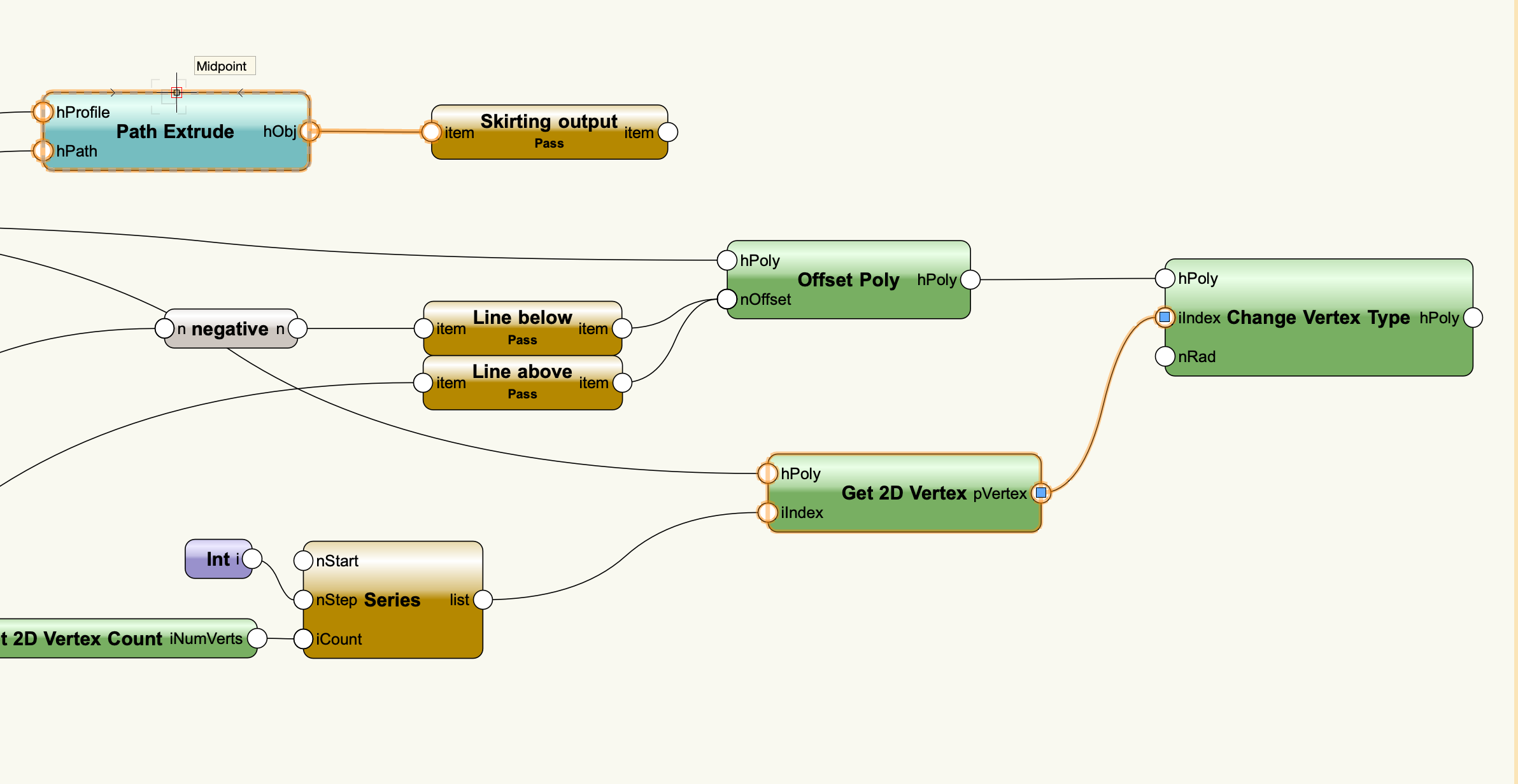
One other thing - the Sequence node actually creates a list that is too long based on the number of vertices. The Series node works better.
Fillet multiple polys v2021 SB.vwx
-
 2
2
-
-
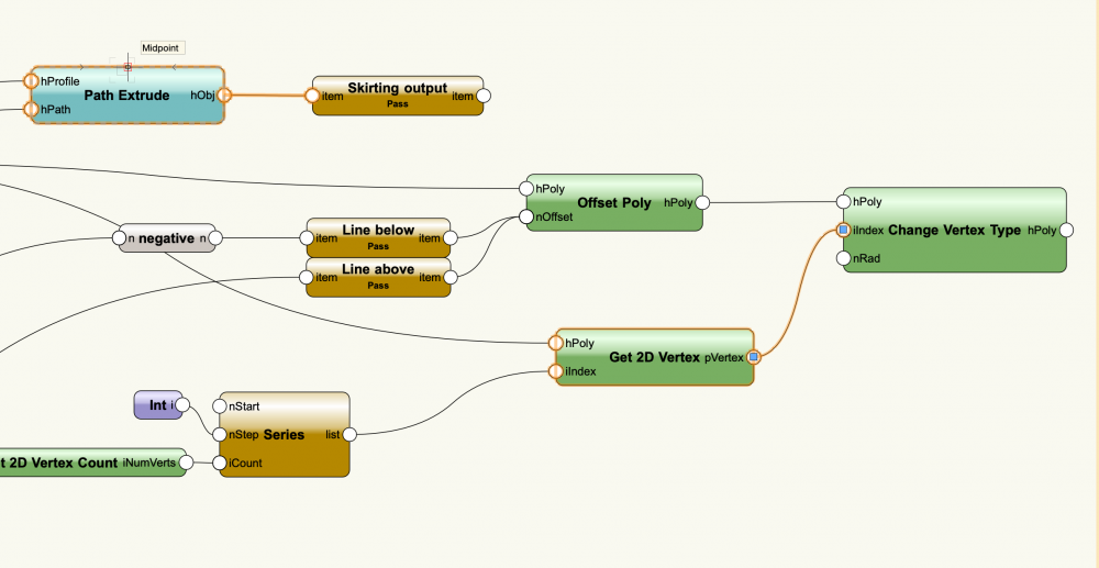
You were almost there. You got the list of vertices correct, but the hPoly input of the Change Vertex Type node needs to have the correct polys compared to the list of vertices. What I did was I "repeated" each of the poly handles so that the polys and vertices matched. I didn't duplicate them, I just repeated their handles in a list so the node would know to go back to that poly each time. This is one of those times when it is important that you have the same list lengths going into the inputs because if they are not the same length, the last item in the shorter list will simply be repeated over and over until the longer list is complete.
Fillet multiple polys v2021 SB.vwx
-
1
-
-
I am not aware of any way to automatically ungroup geometry. FYI, the reason that Marionette scripts create groups is so that the geometry is "tied" to the script. The script not only creates a group, but names that group with a name related to the script, so that when the script runs again, the named group is deleted and replaced.
-
2
-
-
@Sebasrougs when you create your list of points to move your duplicates, you need to use the Mix2 node and select the Cross Reference mode in the dropdown. You need to create XYZ coordinates of every possible combination.
-
1
-
-
What you are talking about is the same idea as this file. This takes loci and nearby text taken from a survey and converts them to the Existing Tree PIO. It could be adapted to the Space object. Because the Space is a path-based object (each Space shape is potentially unique, based on a path), you would have to adjust the script a little.
-
2
-
-
Most nodes new nodes will work in 2016 because they use pre-existing python functionality, but some nodes have Marionette-specific functionality, such as the Valve node, the Slider node, and the Chart nodes.
-
Hello,
You need to use the node "Get Font ID" between the String node and the iFontID port of the Set Char Properties node. When in doubt, check that the prefixes of the output and input ports match. (They won't always match because of generic prefixes like "item" and "list", but they can be helpful in these situations.)
-
I am coming in a little late to this conversation but I created a network for Landmark users a while ago that sounds very similar to what you want. Now that you have gotten started, you may not need this, but it might still be a helpful resource.
-
Once you move the control points of a Marionette object, they will stay that way. What I would recommend is naming the Control Point node so it's values will appear in the OIP of the Marionette object. You can manually reset them there if you need to.
-
Hi @halfcouple - you are correct in that you have to use a Menu Command to run a network on selected objects, you cannot do it with a regular network or a Marionette object. You can give yourself access to options in a menu command by using the nodes in the User Interaction folder in the Resource Selector. If you replace the regular input nodes with these dialog nodes, when you run the command, dialogs will pop up for each node asking what you want the parameters to be.
-
Yes, you can use a Control Point 2D node. I have added it to one of your Marionette objects.
-
1
-
-
I have edited the node so that the "result" shows up and the associated data tag is now an output as well. This network will work when running it on a single design layer, but because of how Marionette works (creating groups of objects), placing them on multiple layers at the same time is rather tricky and I don't recommend it. Also, I don't recommend trying to use this with viewports. If you are tagging objects in viewports, I think using the data tag as-is works better than trying to script it.
-
Hi @Martin Lerch, I tested it and it appears to work great. The issue that you will have is that any geometry created by a Marionette script will be grouped. after the script is run and you ungroup the data tags, they appear to be associated properly with the space.
I would recommend having the data tag also be the output of the script, that way you can manipulate it further along in the script (after it has been associated) if you wish.
-
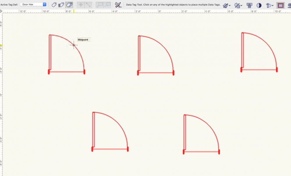
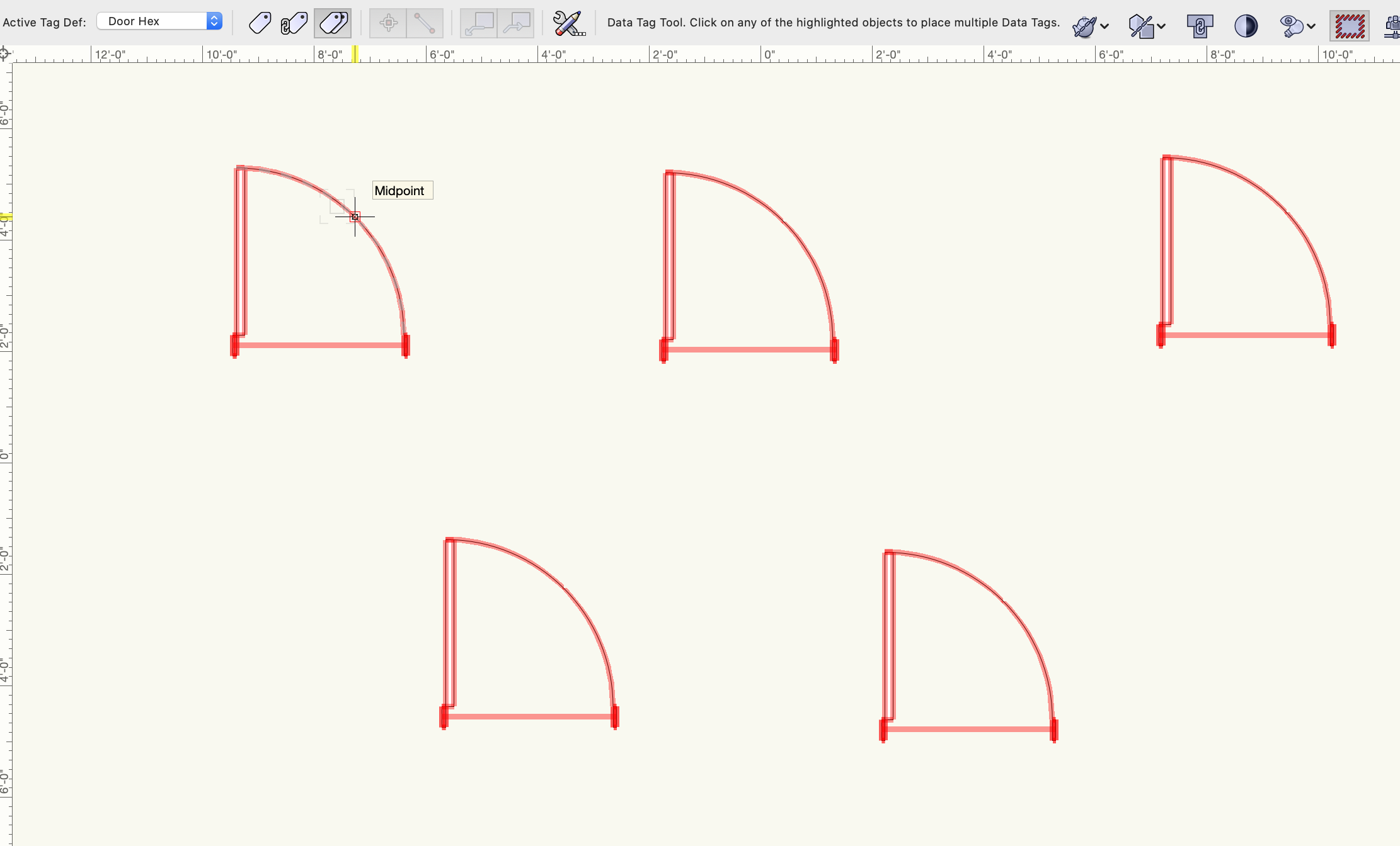
You can do this by choosing "Select Eligible Objects Mode" in the Mode bar of the Data Tag tool. If your tag is set to read a field from the Space object, you can hover over a Space with that Data Tag style selected and all spaces will highlight red. This works with any object type that the Data Tag is looking for. I took a screenshot of it using Doors and a Door-specific tag.
-
Hello Martin,
There are no default nodes, but there are a few scripting calls that have been added to Vectorscript and Python in 2019. You can find them here. https://developer.vectorworks.net/index.php/VS:Function_Reference#Data_Tag_Interface_Library
In order to place a data tag, you could use the Symbol node and then I imagine you could create a custom node that uses the first command, https://developer.vectorworks.net/index.php/VS:DT_AssociateWithObj, to associate it with a Space. I think this would work if you are placing these Data Tags in design layers, but if you are trying to place them in the Annotation Space of a viewport, I would recommend adding Data Tags manually. There is a way to tag all relevant objects at once, so I imagine a script wouldn't bring much added efficiency.
-
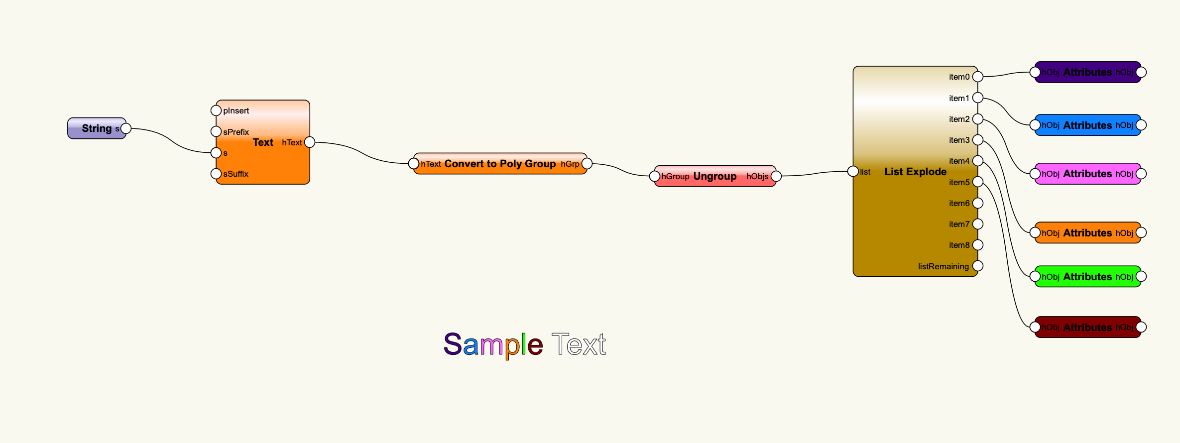
Yes, there is a node called convert to Poly Group. Here is a quick example of how to use it.TextToPoly.vwx

-
Hey @Todd Drucker - I am excited to see you have started with Marionette! The first thing to remember though, is although Marionette is the same type of tool as Grasshopper, it's based off of Vectorworks' functionality and just as Grasshopper is based off of Rhino's functionality. Marionette doesn't really have an equivalent to "Morph" - some people have created arrays along surfaces with it, but they usually have to do it mathematically. There is however a command in the model menu called "Create Surface Array" that pretty much does this. It take a 2D or 3D object and arrays it across a NURBS surface, So I think you might have better luck if you model the column using curves and a loft surface (you can create this with Marionette if you like or just model it manually), the modeled pattern, and then use the Surface Array command. Tip, if you convert the 3D object to a mesh, it will morph around the Surface Array.
-
I think you could try using a Mix2 node and choose the Cross Reference mode in the Object Info palette of the node. The important thing for list handling in this instance is that there are the same number of values flowing to each input. The Mix 2 node allows you to repeat values in the way that you want.
-
1
-
-
Actually, if you uncheck smooth corners, you don't need the Change Vertex Type node at all, so you can remove that whole section.
-
also, you should remove the Get 2D Vertex node and instead connect the Series node directly to the iIndex input of the Change Vertex Type node - its looking for integers, not points.
IFC Help Needed
in Marionette
Posted
To get the right values, type the field names into the String nodes exactly as you see them here: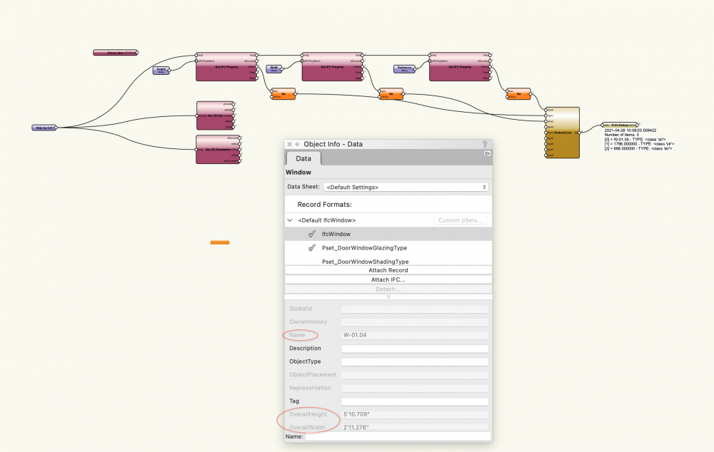
I have updated the file.
Cavity Barrier-SB.vwx