
Bruce Kieffer
-
Posts
2,817 -
Joined
-
Last visited
Content Type
Profiles
Forums
Events
Articles
Marionette
Store
Everything posted by Bruce Kieffer
-

Align objects in right ISO.
Bruce Kieffer replied to Bruce Kieffer's question in Wishlist - Feature and Content Requests
I just did. That's not what I want. I want simple. I want to align the tops relative to the last object selected, and I want to do that in right ISO view. -
Align objects in right ISO.
Bruce Kieffer replied to Bruce Kieffer's question in Wishlist - Feature and Content Requests
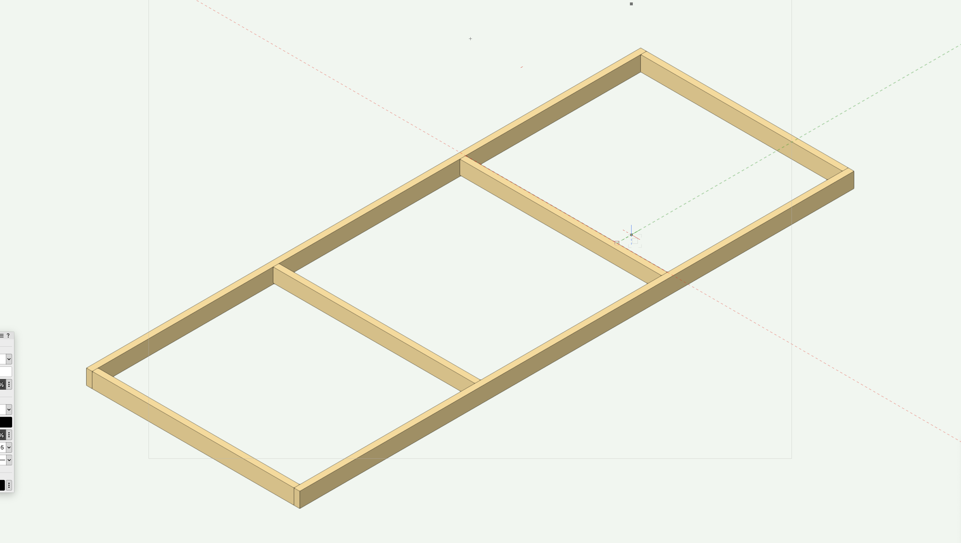
Let me show you. I want to align the middle rails tops to the end rails tops rendered shaded. The rails are not the same width. Front view hides the parts. Right ISO I can see both, select them, but align tops aligns somewhere else.
-
Align objects in right ISO.
Bruce Kieffer posted a question in Wishlist - Feature and Content Requests
Wow would it be sweet to be able to align objects in 3D right ISO. -
One of our community group members asked me about making this so I revisited my drawing for 2007. How the serpentine polyline is created does make a difference how the shape extrudes. The shape I had in my 2007 drawing did not work. When I extruded that it created a closed on the bottom object. That was obviously something either I did not care about back then, or I could not resolve back then. Double click to enter history mode and you will find polyine shape. There are other ways to do this. The file is attached. Corregated.vwx
-
How do I get Shaded to show all lines?
Bruce Kieffer replied to Bruce Kieffer's question in Troubleshooting
Yes, the viewing angle does affect line visibility in this instance. Duh, it should have no affect though. -
How do I get Shaded to show all lines?
Bruce Kieffer replied to Bruce Kieffer's question in Troubleshooting
I do think this is a Mac bug. -
How do I get Shaded to show all lines?
Bruce Kieffer replied to Bruce Kieffer's question in Troubleshooting
I changed the crease angle many times. I could see different results. I set it to 20 and that shows the lines. Set to 1 works too. OK, but this crease angle thing makes no sense to me.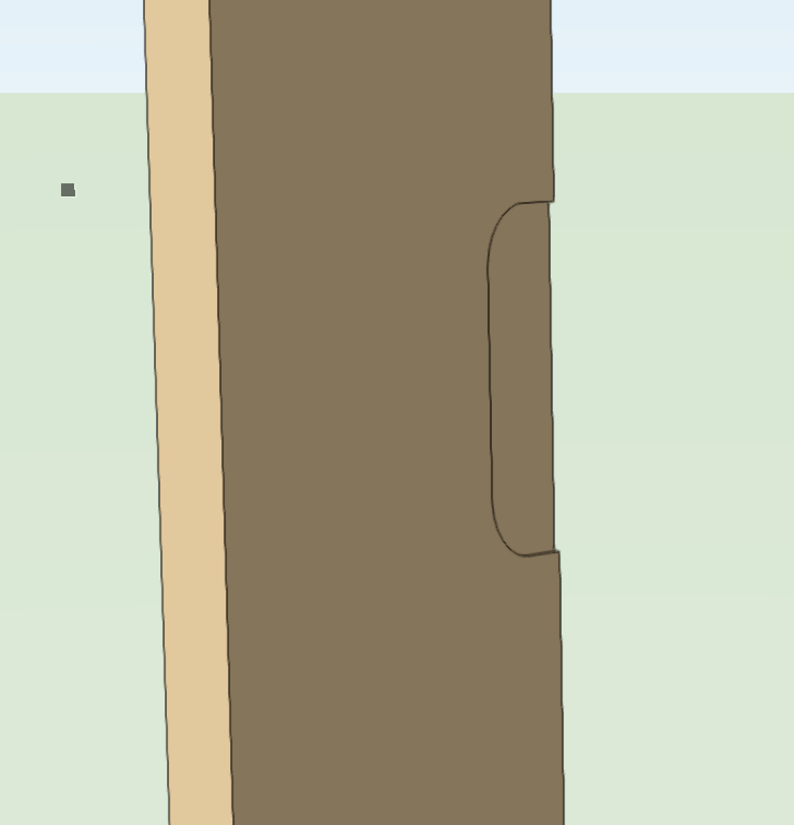
-
How do I get Shaded to show all lines?
Bruce Kieffer replied to Bruce Kieffer's question in Troubleshooting
I do think this is a bug. I think I have the shaded settings correct.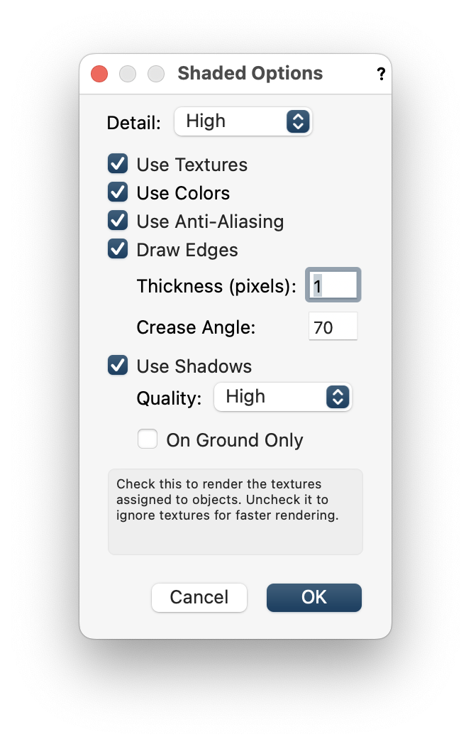
-
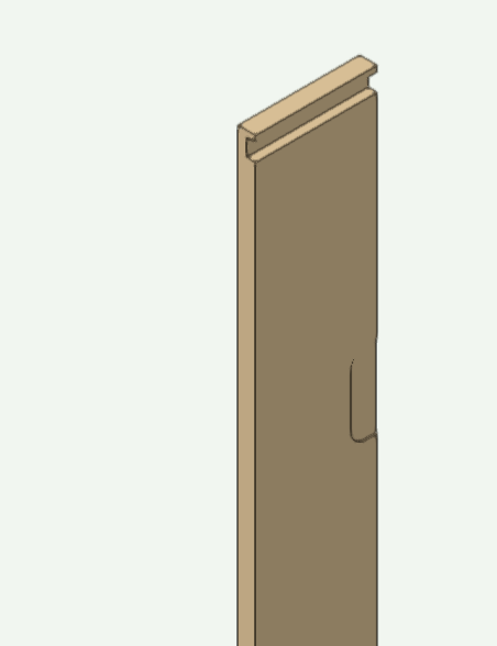
You see the lines that define where the hinge mortises are cut on this door jam, but those lines are not complete. This problem seems to have appeared since the last SP update. How do I get all the edges of the mortise cuts to show?
-
Call VSS. They can help figure out why.
-
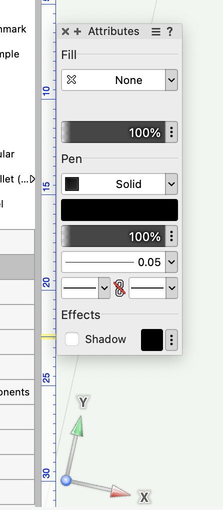
I just found the XY axis indicator hidden under my Attributes palette. Is there a way to change where that indicator appears?
-
Set Shaded render to Detail very high by default?
Bruce Kieffer replied to Bruce Kieffer's question in Troubleshooting
Thanks @Tom W.I found the problem. Some of my saved views were saved with the Shaded Detail set to Low. When I change those to Very High then the setting sticks. -
Set Shaded render to Detail very high by default?
Bruce Kieffer posted a question in Troubleshooting
Is there a way to set Shaded for Detail Very High by default? It seems to revert to low a lot for me.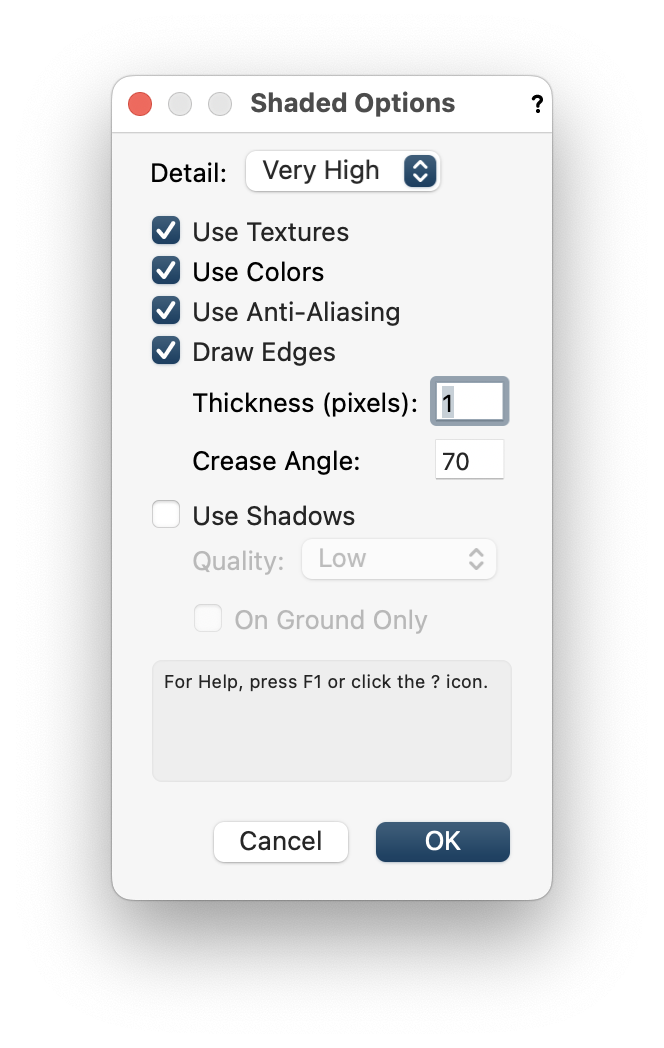
-
The solution I have so far is to save the new WP, name it differently, and then delete the old one. It's inefficient.
-
@michaelk, I don't think you understood my question. I want to create a new working plane and then tell a previously saved working plane to now take on the attributes of the newly created working plane.
-
Is there a way to redefine a working plane like redefining a saved view?
-
That's why! Thanks @PatStanford
-
I have the Menu/Modify, the contextual menu, and the edit working plane methods working to do this now. Thanks, but I can't figure out how @Tom W.'s way works? I can select the working plane, but I don't get any arrows to move? This is what I see:
-
I'm using the NURBS curve idea to set working planes. Every so often I get a working plane view that is upside down. Is there a way to adjust the working plane to flip it over?
-
Now that is nice. Thanks.
-
I tried defining a working plane on a line. It does not work.
-
I realize one way to rotate around a line would be to set the working plane to the line. Is there any other way to do this?
-
Typical Worksheet Criteria to count visible objects?
Bruce Kieffer replied to Bruce Kieffer's question in Troubleshooting
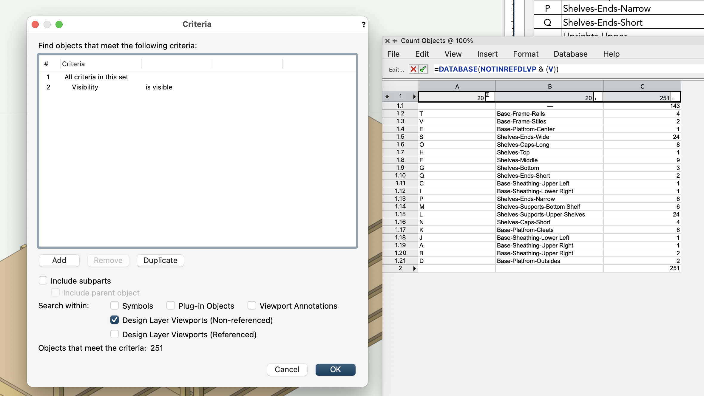
I figured it out. When the criteria is Visibility is visible, then Vectorworks counts the objects that are visible as defined in the navigation palette, and that includes the visibility of layers. My problem was I placed the worksheet on another design layer, Design Layer-2, and expected it to count the visible objects on the Design Layer-1, but I had the Layer Options set to Active Only, so even though the Navigation Palette has some classes set to visible, when the layer is not visible, then Vectorworks can't count the visible class objects in that layer. Now that I understand this it does make sense. Also, I find it best to place the worksheet on a sheet layer in this case and use Multiple View Panes, then I see the worksheet face on in one pane and the layer and visible objects in the other pane. The worksheet counting is correct that way. -
Typical Worksheet Criteria to count visible objects?
Bruce Kieffer replied to Bruce Kieffer's question in Troubleshooting
I have it working, but how I did that is a mystery to me. I would think that visible means what I can see, but the worksheet will pick up objects that I can't see. This appears to be related to where the material and record is attached to a symbol. I'm working to figure that out. In the meantime this setup in my screenshot does work to give me the info I need. If I remove the Record criteria then symbols that are not visible get counted in the worksheet.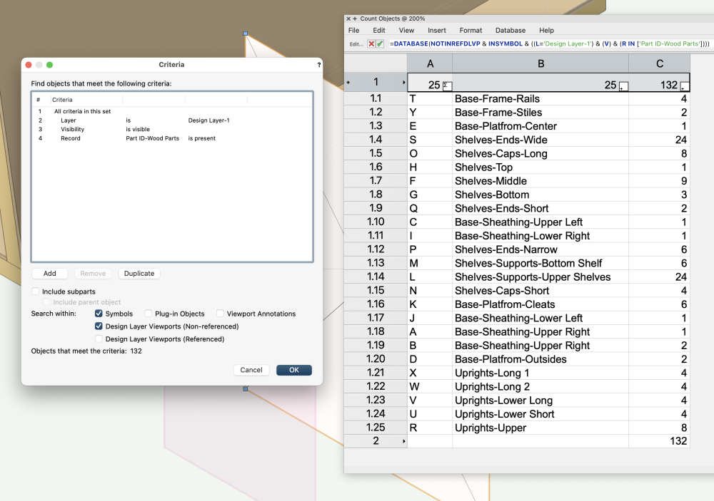
-
Typical Worksheet Criteria to count visible objects?
Bruce Kieffer posted a question in Troubleshooting
I can't make this work. I want to count the visible objects in my Design Layer-1. Using Visible as criteria does not change anything in the worksheet. There are 87 visible object, yet my worksheet says 108. Class options settings affect the worksheet. I want to count what I see. What do I have wrong?