
Bruce Kieffer
-
Posts
2,817 -
Joined
-
Last visited
Content Type
Profiles
Forums
Events
Articles
Marionette
Store
Everything posted by Bruce Kieffer
-
 I only care about subtractions like when I drill a hole in a panel. Solid additions are another subject.
 -
I think that is exactly what I want. I believe an object's dimensions should be irrelevant of it's rotation. And when a hole is drilled through it rotated or not it does not change size. I can't imagine any situation where a person would not want the true dimensions of an object.
-
Hide Class Command Needed.
Bruce Kieffer replied to Bruce Kieffer's question in Wishlist - Feature and Content Requests
Yes, The visibility Tool which @rDesign mentioned above. I've been using it and it is better than a contextual menu hide command. More powerful. Cool how the double click the icon functions work. Check out the tool's settings, that's where you will find those options. -
The only solution I see is for Vectorworks to improve this. Please upvote this wish.
-
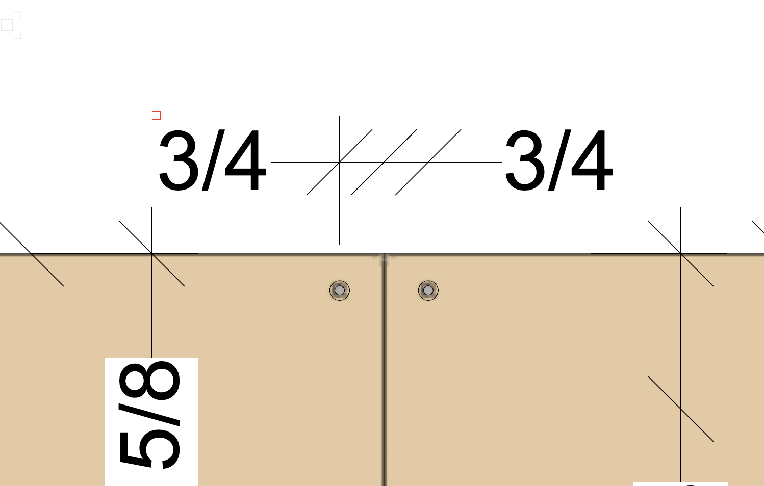
This issue really causes me a lot of extra work. In my work I need to create many extrusions that are not oriented on a strict 0 x or 0 y axis. Those objects do calculate their dimensions correctly until I subtract something from them. To make that work I have to rotate the object to 0, subtract the objects, then rotate the subtraction back to its original rotation. And this gets worse with symbols. In the real world when I drill a hole in a 3/4" think panel, that panel remains 3/4" thick, irrelevant of how the panel is oriented when I drill the hole. That's what I wish Vectorworks did.


-
Hide Class Command Needed.
Bruce Kieffer replied to Bruce Kieffer's question in Wishlist - Feature and Content Requests
It sure does work! That's perfect. Now I just need to remember to use that tool! -
Hide Class Command Needed.
Bruce Kieffer posted a question in Wishlist - Feature and Content Requests
It's way too difficult to hide a visible class without locating the class in the navigation palette. I can right click an object and activate the class, but often that class is buried in my navigation palette hierarchy, so it's useless to activate it because I still have to find it. A right click hide class command would solve this.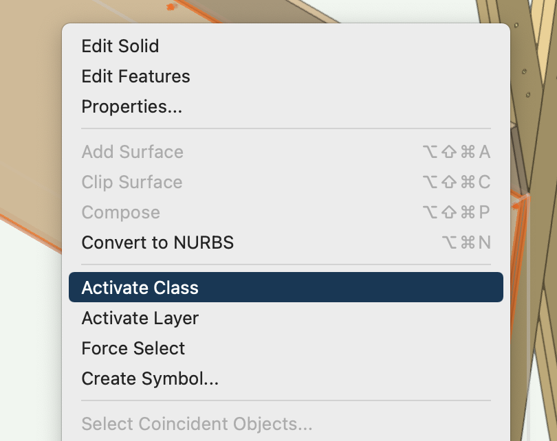
-
How can I create a Viewport of a symbol?
Bruce Kieffer replied to Bruce Kieffer's topic in General Discussion
I used Pat's suggestion. It works well. I placed all the objects and symbols that need dimensioning on one "Parts Dimensioning" layer and made viewports from there. Then I set my worksheet criteria to ignore that layer. It's rather simple. -
How can I create a Viewport of a symbol?
Bruce Kieffer replied to Bruce Kieffer's topic in General Discussion
That was the first thing I tired. Create a VP from a symbol. That would solve the problem. Until then, I think Pat's suggestion is the simplest, although I appreciate all of the other suggestions. -
How can I create a Viewport of a symbol?
Bruce Kieffer replied to Bruce Kieffer's topic in General Discussion
I will try that. Thanks. -
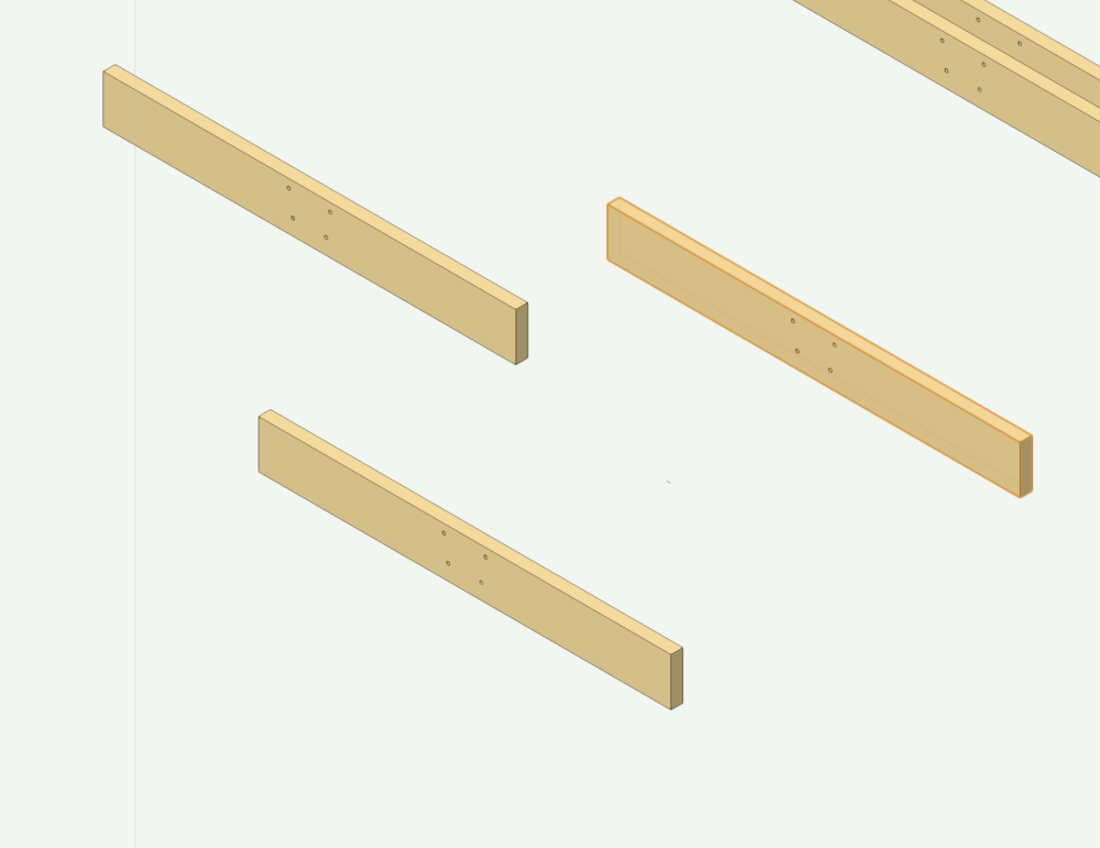
I want to dimension this symbol without adding another instance on another layer. Is there some way to isolate one instance in my layer and create a viewport of that? I know about cropped viewports and I know I could create another class to isolate one instance, but cropped won't work because the objects are not aligned, and adding another class is not what I want to do. I'm counting the symbol instances in a worksheet, so adding more just to dimension them is not an option. Theses objects are all the same symbol. I want to dimension just one of them:
-
Why is shaded render in a viewport so bad?
Bruce Kieffer replied to Bruce Kieffer's question in Troubleshooting
I did try that and it works, but it slows things down significantly. I've come to realize that the appearance of the VP on the SL indicates what the print out will look like. That's fine with me. -
Why is shaded render in a viewport so bad?
Bruce Kieffer replied to Bruce Kieffer's question in Troubleshooting
The file I posted is a stripped down version of my file, but it shows the pixellated viewport that same as I see with my full version file. The dimension of my components are the dimensions they need to be. I can't change them to accommodate Vectorworks rendering better. I suppose I need to realize that a sheet layer is used for printing, and therefor it needs to be a certain DPI to work with a printer. I also assume the Shaded in a design layer is adjusted for screen resolution which is far greater than a printer's resolution. I think that is the answer to my question. I guess I just need to accept that and live with it. It does not affect my work, I just wish it looked better. -
Why is shaded render in a viewport so bad?
Bruce Kieffer replied to Bruce Kieffer's question in Troubleshooting
Here's a dumbed down version of my file. Viewport only Sheet layer is set to 300 DPI. I want this to render better.vwx This is what I see:
-
Why is shaded render in a viewport so bad?
Bruce Kieffer replied to Bruce Kieffer's question in Troubleshooting
I have an M1 iMac. What I don't understand is why is Shaded super fast and sharp in a design layer, but not in a sheet layer, even when the sheet layer is set to 300 DPI. I see no reason why. -
Why is shaded render in a viewport so bad?
Bruce Kieffer replied to Bruce Kieffer's question in Troubleshooting
I just set the SL DPI to 4800. That does render a lot better, but the time it takes to render shaded is far too long. I think this could be improved in Vectorworks. -
Why is shaded render in a viewport so bad?
Bruce Kieffer replied to Bruce Kieffer's question in Troubleshooting
I tested this in a DLVP. It does render much better, but the limitations of the design layer verses a sheet layer make it unusable in my situation. -
Is there a limit to the classes hierarchy?
Bruce Kieffer replied to Bruce Kieffer's question in Troubleshooting
I can live with that. I just need to rethink my classes and maybe adds some layers. -
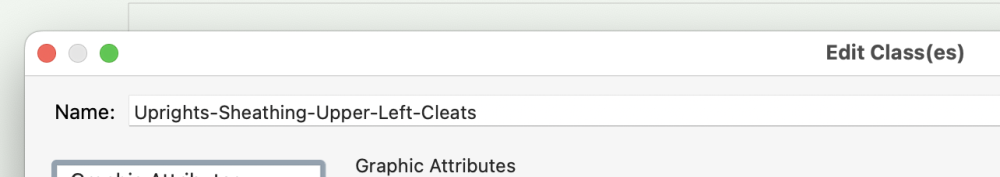
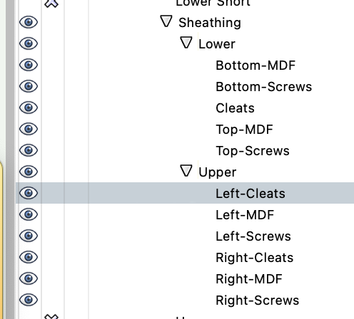
I'm trying to set up a three deep classes hierarchy without luck. I do have the dashes correct, but Vectorworks appears to only go two deep on the hierarchy. I want the Sheathing Lower Bottom, the Sheathing Lower Top, the Sheathing Upper Left, and the Sheathing Upper Right grouped with disclosure triangles. I tested with a new document too, same results.
-
Why is shaded render in a viewport so bad?
Bruce Kieffer replied to Bruce Kieffer's question in Troubleshooting
I agree. My Shaded design layers are fine. For what I am doing RW is way overkill. I'll report back after I test the DLVP. -
Why is shaded render in a viewport so bad?
Bruce Kieffer replied to Bruce Kieffer's question in Troubleshooting
I just tested using Renderworks as the background render. Horrible there and horrible in the design layer. It must have something to do with my using color on the objects rather than textures. Shaded looks good in my design layer. Next I will try a design layer viewport. -
Why is shaded render in a viewport so bad?
Bruce Kieffer replied to Bruce Kieffer's question in Troubleshooting
@Christiaan, Both of those changes help. Thanks. I think if I want a really good render in a viewport, then I have to use Renderworks as the background render. -
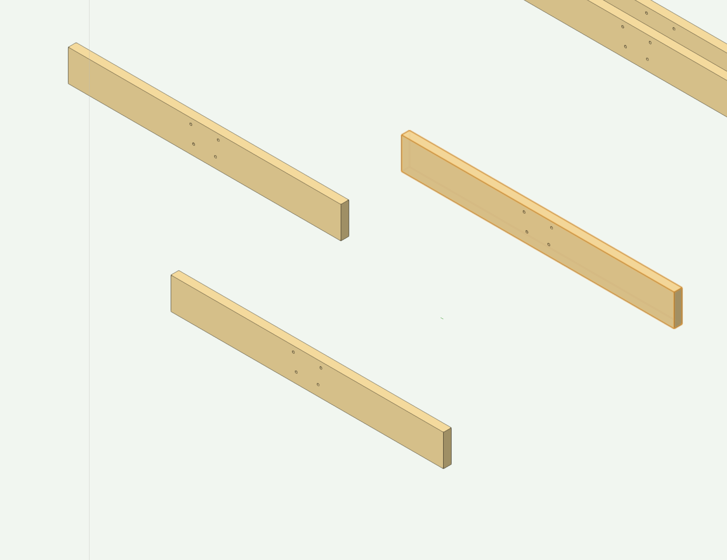
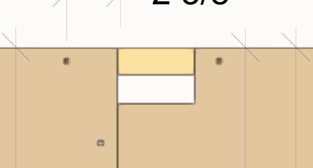
This object is 3/4" thick and rotated 10°. If I subtract something from it, then Vectorworks thinks the thickness is 10-9/16". I have to rotate the object to 0°, do the subtraction, then rotate it back to 10° to make Vectorworks think it is 3/4", which is it's true thickness. There's no reason Vectorworks can't do this correctly.

-
Is there a way to make a viewport shaded render look better than this? I have the sheet layer set to 300dpi, and the viewport background shaded render set to Very High.
-
Align objects in right ISO.
Bruce Kieffer replied to Bruce Kieffer's question in Wishlist - Feature and Content Requests
I don't understand why it doesn't work. It's like some remnant of screen plane. Why does it matter what the view is for alignment. I say align the object tops in any other view like front, right, left, back, all 3D views, and align works there.But in right ISO, where I can actually see the parts, and it won't align.