line-weight
-
Posts
3,755 -
Joined
-
Last visited
Content Type
Profiles
Forums
Events
Articles
Marionette
Store
Everything posted by line-weight
-

3DConnexion SpaceNavigator Configuration
line-weight replied to PVA - Admin's question in Troubleshooting
I've had a spacemouse pro for several years and there are various points in time where there have been problems - usually to do with upgrading to new versions of VW or most recently connected with Big Sur. These usually end up eventually getting fixed via a SP from Vectorworks or a driver update from 3dconnexion. For now my spacemouse is working fine, but there's always a background worry that something's going to break, each time you do any kind of update/upgrade. This is not ideal, but it's useful enough to me that I just tolerate it. It's also not ideal that 3dconnexion seem to have a monopoly in the market for such devices which means you are entirely dependent on them being bothered to fix things when they go wrong. -
It seems to me that 95% of the problems with levels / stories are to do with user interface design. The basic thing is fairly sound and not actually all that complex. But as usual, VW somehow manages to implement it in a way that is almost as if it's deliberately designed to be as confusing as possible.
-
Does this mean that the "compose" command remembers the classes of the individual components even if they are different from whichever class the composed polygon ends up in? That's useful to know for future troubleshooting.
-
Horizontal sections: display certain 2d components only?
line-weight replied to line-weight's topic in Architecture
In top plan it looks like this (It's actually not inserted into a wall, but sitting on top of a shortened wall, because that's the most convenient way to model this particular building) I'll send you the file privately.
-
Horizontal sections: display certain 2d components only?
line-weight replied to line-weight's topic in Architecture
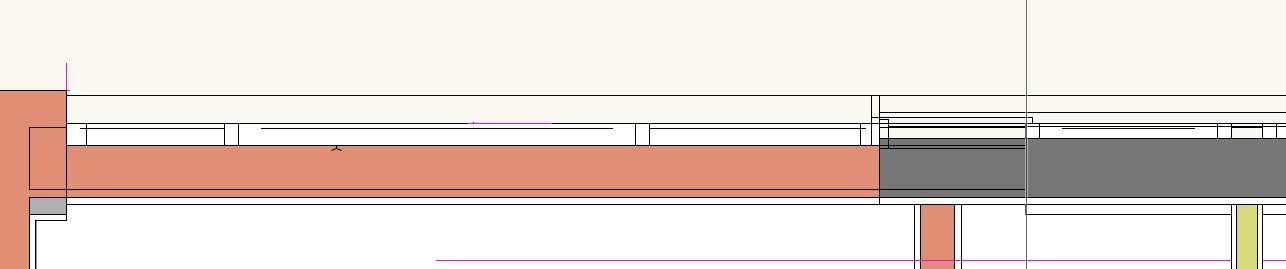
On the left is with 2d components, on the right without. At this stage I'm doing 1:50 floorplans as "merged" sections. I expect there will be a separate bunch of issues with non merged, but once I get to that level of detail I'll probably have to model the windows myself anyway, because the VW ones are so hopeless. What's wrong is 1) Missing lines 2) Lines that shouldn't be there 3) Cut plane in places it shouldn't be Here a bit larger: Neither version is exactly what I want (for example, I'd quite like the cutplane fill not to apply to the glazing elements) , but the non 2d component one is much closer. Maybe you will tell me things can be improved if I change things in the window settings, in which case I'd be interested to hear.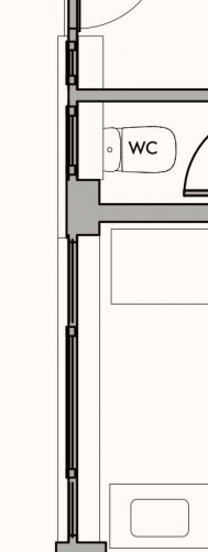
-
I'm trying out "horizontal sections" as opposed to just regular sections taken horizontally, for the first time. As I understand it, a significant difference is the ability to show the '2d' representations of certain objects, like you would in top/plan, rather than simply slicing the 3d component of those objects. My question is, can I choose to do this for certain objects only, or is it all or nothing? For example, ticking "display 2d components" gives me something workable as far as doors are concerned, but windows are a disaster and I prefer how the look when they are just done as a horizontal slice through the 3d geometry. So is it possible for me to choose to have the 2d components of door objects shown, but not of window objects?
-
Multi-storey building all in one storey - would this work?
line-weight replied to line-weight's topic in Architecture
I just tried this - but without success. -
Multi-storey building all in one storey - would this work?
line-weight replied to line-weight's topic in Architecture
Not sure it can be blamed on conversion from earlier version - the drawing I'm working on at the moment I started completely fresh in 2021. I'm not quite sure yet, but I think that when these lines show up in my OpenGL views, they don't necessarily also appear in my hidden line viewports. -
Do you manage to work with multiple view panes?
line-weight replied to line-weight's topic in General Discussion
Not just me then! -
Multi-storey building all in one storey - would this work?
line-weight replied to line-weight's topic in Architecture
Yes, it's a two component wall, using a wall style. Turned out it was because I didn't actually have a texture assigned to either of those components. When I did that, the options became editable. And ticking the "use world Z" box did make the line go away as you suggest. It doesn't come back when I then untick the box. -
Multi-storey building all in one storey - would this work?
line-weight replied to line-weight's topic in Architecture
Hm, I have walls by component too, but it's greyed out nonetheless. -
Multi-storey building all in one storey - would this work?
line-weight replied to line-weight's topic in Architecture
Fairly sure it's not an XY issue in this case because it's sorted by only adjusting the Z height. -
Multi-storey building all in one storey - would this work?
line-weight replied to line-weight's topic in Architecture
That's a setting I've never looked at or used before. But it seems to be greyed out for my wall objects anyway? -
Multi-storey building all in one storey - would this work?
line-weight replied to line-weight's topic in Architecture
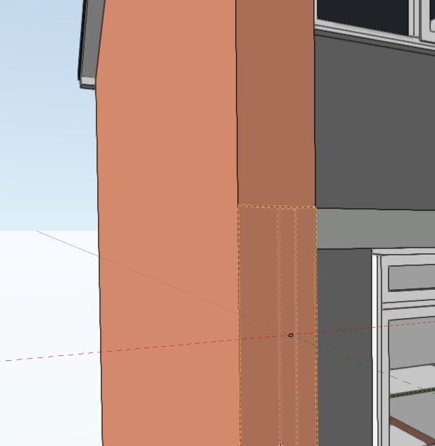
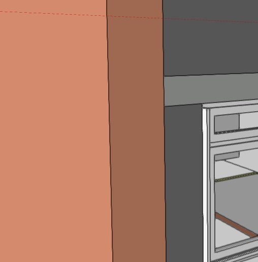
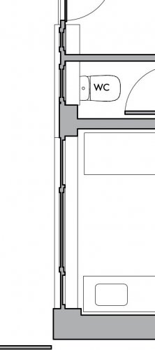
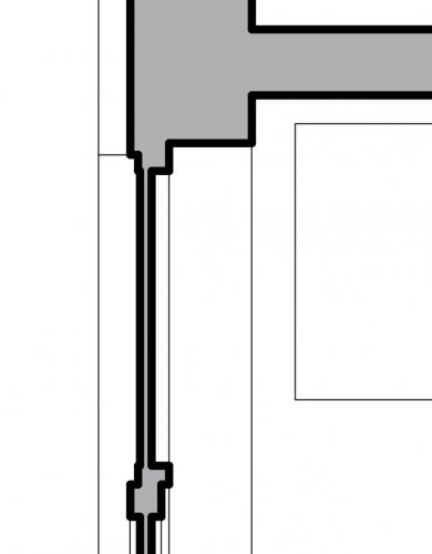
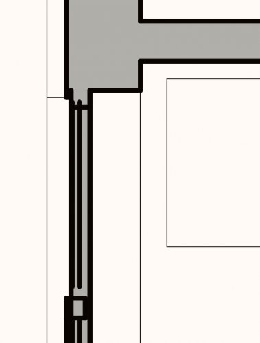
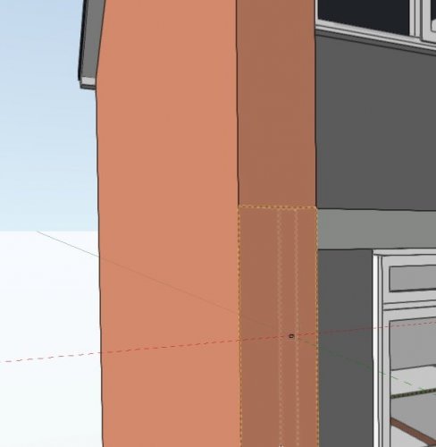
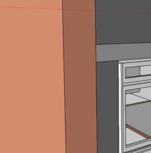
A small problem I am finding: That line should not be there. It's between two wall objects. They are on different design layers, but the bottom of the upper wall is bounded to the same level as the top of the lower wall. If I manually grab the bottom of the upper wall, so I can resize it up and down, and then snap it to the top of the lower wall, the line disappears, as it should. In the OIP, both objects are still shown as bounded to the level, with an offset of zero. So as far as the OIP is concerned nothing has changed, but the line has now disappeared. This doesn't seem to happen in all instances (for example it hasn't happened around the corner you can see in the screenshot), just some places.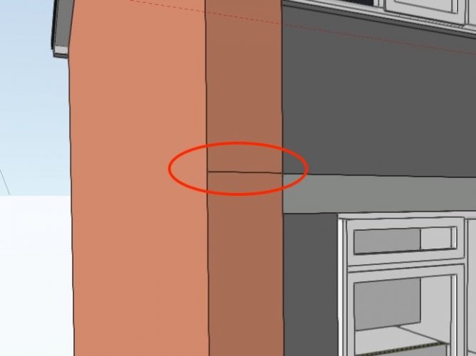
-
Do you manage to work with multiple view panes?
line-weight replied to line-weight's topic in General Discussion
Coming back to this 6 months later and having upgraded from 2018 to 2021, and got a new mac - I still have lots of problems with floating view panes; just general buggy behaviour. I mostly try to avoid doing any actual editing in a floating view pane, various things like snaps often don't work properly. So I sometimes use them to watch what's happening in a different view, whilst doing work in the main window. Saved views often don't activate properly. Additionally, I notice that just having a floating view pane open can make OpenGL navigation glitchy in the main window. I'd hoped that the "smart options display" thing in 2021 would be a bit of a game changer for working across different monitors, because it would save me having to come back to the main window all the time to select tools and so on - but I can't really take advantage of it because of the unreliable behaviour once I'm working in the floating pane. Will any of this stuff ever get dealt with or will the "floating view pane" just be another thing to die a slow death, used by hardly anyone? -
Multi-storey building all in one storey - would this work?
line-weight replied to line-weight's topic in Architecture
It feels a bit like it doesn't really want you to make your own level types at all. But the first thing I wanted to do was get rid of all the default names and use ones that were meaningful/relevant to me. Normally VW is quite good for this kind of customisability. -
Multi-storey building all in one storey - would this work?
line-weight replied to line-weight's topic in Architecture
One annoyance already noted: it doesn't seem possible to re-name 'levels', as far as I see. So whatever name I choose for it, I am stuck with for good, unless I want to make a new one, and then manually re-associate all walls etc with that one. -
Units and rounding: downsides of excessive precision?
line-weight replied to line-weight's topic in General Discussion
It is sometimes, but then as a designer you can waste a lot of time trying to second-guess contractors' preferences, availability of materials/products and so on. You have to find some kind of middle way between insufficient and excessive 'accuracy'. Often the skill is in how you present the setting-out dimensions. If you are thoughtful about it, you can try and do it such that if things like actual timber sizes are different from your assumptions, then it'll be a non-critical rather than critical dimension that changes. Of course many of us have plenty of experience of working with builders who have no intention of looking in detail at the drawings anyway! -
Units and rounding: downsides of excessive precision?
line-weight replied to line-weight's topic in General Discussion
My experience when I did a bit of building work myself was that it's not as consistent as this! I'd get timber from one source and then some more from another, and then the studs would be 2 or 3 or 5mm different in one or other dimension, which is a problem if you are using them to frame the same bit of wall or roof. I learnt to be very careful when ordering and check what their 'actual' rather than nominal size was. -
Multi-storey building all in one storey - would this work?
line-weight replied to line-weight's topic in Architecture
Yes, a big advantage of it happening automatically is not just time saving but makes it much easier to spot errors - if you know the level is always correct and can't be moved accidentally then you can easily see when things are not in the right place (same with vertical grid lines). -
Units and rounding: downsides of excessive precision?
line-weight replied to line-weight's topic in General Discussion
We still have that here in the UK, you'll commonly ask the builder's yard for a 2" by 4" but what shows up is not 2" by 4". It might also be sold as "nominal 50mm x 100mm" or something like that, and again what shows up won't be that. Unfortunately it can be all sorts of things, like 45mm x 95mm or 45mm x 90mm or 47mm x 97mm and so on, and I'm often not 100% sure what's best to actually draw. In some cases it's not really critical and in some it is. -
Units and rounding: downsides of excessive precision?
line-weight replied to line-weight's topic in General Discussion
But it seems to me that it is more likely that a dimension will be 6202mm or 6204mm or 6208mm than 6200mm. And then what do you say, 6m comma 20cm-and-2-mm? I just say, six, two hundred & 2. Or six, 2-0-2. -
Units and rounding: downsides of excessive precision?
line-weight replied to line-weight's topic in General Discussion
In my head I'd be thinking 6200mm rather than 6.2m, at least while I'm drawing. In my head it's "six two hundred" rather than "six thousand, 2 hundred". Of course, we can write 6,200mm or 10,450mm which can make it more easily readable but runs the danger of causing confusion when read by a continental type who reads the comma as a decimal point, so I have got out of the habit of writing the comma. -
Multi-storey building all in one storey - would this work?
line-weight replied to line-weight's topic in Architecture
Hm, so not even this is possible at the moment? -
Multi-storey building all in one storey - would this work?
line-weight replied to line-weight's topic in Architecture
I'm also realising that because 'levels' can only really be used by a few object types, they are not as useful as I was imagining they'd be. I'd like to be able to (for example) extrude a rectangle to create a solid, and then send it to sit relative to a certain level. Another question, which I've not investigated... if I do set up levels, can I then use them automagically in sheet layer viewport annotation to quickly and accurately show significant levels like FFL and so on? Because that would save some time and help with drawing coordination.