


LarryO
-
Posts
428 -
Joined
-
Last visited
Content Type
Profiles
Forums
Events
Articles
Marionette
Store
Posts posted by LarryO
-
-
As Pat says, VW will choke on that many raw points expressed as individual loci.
I was able to generate 250,000 loci in a few minutes but only by creating and grouping them in blocks of 10,000 (100x100 array) and duplicating that block into a 5x5 array of blocks.
I could post a simple layout of a Pascal procedure but it wouldn't be of much use if you have no programming experience. The following is a portion of a Pascal Procedure and will probably not do anything at best but more likely generate an error because the code is incomplete. Probably an example of poor coding structure too.
PROCEDURE Beam_End;
TYPE
BEAMFORMAT=STRUCTURE
Beam: STRING;
d,w,wb,tw,tf,rf: REAL;
{.d = beam depth, .w = beam width, .tw = thickness web,}
{.tw = thickness top flange, .rf = radius flange, .wb = thickness bottom flange}
END;
VAR {declarations}
CopeBeamSize,BeamSize: BEAMFORMAT;
PIO_Handle,PIO_Record,PIO_ParentWall,hBeam,CopeBeam_Handle,hDim: HANDLE;
TopET,BttmET,NumOfHoles,unitStyle,dimFormat,angPrec,A3: INTEGER;
prec,dimPrec,A1,A2:LONGINT;
LayerScaleFactor,FileUnits,CopeTop,CopeBttm,DimStrOffset,Y1,Y2,
X_HolesCL,YHoleSpacing,FirstHoleOffset,GussetWidth,A4,rTemp1,rTemp2,HoleOfset: REAL;
FileName,Filepath,PIO_Name,A5,A6: STRING;
BoolResult,showMark,displayFrac: BOOLEAN;
BEGIN
{PROGRAMMING CODE GOES HERE}
{THE FOLLOWING IS A SLICE OF CODE FOR A PLUGIN I WROTE TO DRAW A COPING PROFILE FOR THE END OF A STEEL BEAM}
{HERE I WAS READING IN THE VW's BEAM DATA FILE LINE BY LINE TO POPULATE MY STRUCTURED VARIABLE WITH THE CHOSEN BEAM'S DIMENSIONS}
{Choose Metric or Imperial Beam Data File}
IF unitStyle>=7 THEN BEGIN
FileName:='StructShape_WFlange-Metric.txt';
BoolResult:= FindFileInPluginFolder (filename, filepath);
Units(7); END
ELSE BEGIN
FileName:='StructShape_WFlange-Inch.txt';
BoolResult:= FindFileInPluginFolder (filename, filepath);
PrimaryUnits(2,4,4,3,angPrec,showMark,TRUE); END;
IF BoolResult THEN BEGIN {beam data file found/not found}
{Extract Beam Data}
Open(Concat(filepath,filename));
IF NOT EOF(filename) THEN ReadLn(fileunits);
IF fileunits=1 THEN
WHILE BoolResult & NOT EOF(filename) DO BEGIN
ReadLn(BeamSize.beam,BeamSize.d,BeamSize.w,BeamSize.tw,BeamSize.tf,BeamSize.rf,BeamSize.wb);
IF BeamSize.beam=PBeam_SizeI THEN BoolResult:= FALSE; END
ELSE
WHILE BoolResult & NOT EOF(filename) DO BEGIN
ReadLn(BeamSize.beam,BeamSize.d,BeamSize.w,BeamSize.tw,BeamSize.tf,BeamSize.rf,BeamSize.wb);
IF BeamSize.beam=PBeam_SizeM THEN BoolResult:= FALSE; END;
Close(Concat(filepath,filename));
END;
RUN(Beam_End);
-
It wouldn't be too difficult to create a tool to read in the file's data and place loci at the elevations.
The file's formatting is relatively simple. There are six initial lines of formatting data followed by the lines of elevation data.
Each line begins and ends with a quotation character, and each number in the data lines are separated by a space.
The second line identifies how many rows of data will follow line 6.
The first line identifies how many numbers to expect in each line of data.
Lines three and four give the coordinate location of the lower left corner of the 2d array, (the first elevation number in line seven?) Could this be in meters? (yards or feet?) Line five: I'm not familiar with how cell size is utilized. Maybe it is the marker size, like the diameter of an elevation dot?
Line six tells you the placeholder number used for when no elevation data exists at that location.
A Vectorscript can be written to read in the file and say place a 3d locus at the z location indicated except where the placeholder number occurs. I suppose with a little more effort one could draw connecting lines between adjacent points too.
The script could lay 3d loci out at one metre increments with two REPEAT loops one embedded in the other. Reading in one number at a time from the file.
You would have to determine if each line of data between the quotes represents a row or a column, and confirm that the first digit in line seven represents the elevation data for the lower left corner. It could be the top left for instance, but less likely.
-
 1
1
-
-
What I've come to think that they are is closed tabs that are not hosted in the primary palette.
By primary palette I'm referring to what we would have expected them to be before this new feature was incorporated.
The navigation palette, the object info palette, etc.
So if one tears off the data tab from the object info palette and closes the tab but leaves the obj info palette open. Then under some circumstance that data tab appears off to the side, but unformated, it is not identified with the data tab title or layout. If you go to the pull down menu and activate the data tab one of those generic blank palettes will refresh with the data tab title and layout. I can't seem to identify when the blank palettes are occuring, is it when altering the workspace, opening an existing project file in conjunction with the application???
-
I had these blank palettes too. Mine were hiding off at the very right side edge of my monitor. That was VW2021 before any service packs came out. So it was one of the issues that prompted us to delay installation until SP3. I've have seen the again but they are not as predictable.
My small beef now is that when the tabs are merged as per previous years the tab at the far right in the palette becomes the active tab when ever the palette is reopened. The palette doesn't save the active tab when closing.
-
Could we get viewport functionality to include a display/render 3d symbol definition option?
This would reduce a lot of overhead when doing parts take-off for assemblies. No need of multiple layers and or classes to control visibility and display each part. Each unique part (column, base plate, bracket, cabinet, drawer face, etc.) being a 3d symbol can be orientated about its 0,0 origin (and then be placed throughout layers to form various assemblies). The part can be measured up and annotated with standard view settings (front, back, bottom, left, right iso, etc.) without having all the other parts of an assembly cluttering the background or chasing around for the object in space to place an appropriate crop.
-
I think that this is about the visibility of groups not being taken into account by the hidden line rendering routine used
in thefor section viewportstool. -
Section viewports permit layering of elevations. You can cut off the foreground so distant aspects can be illustrated with lighter weights and colours while the foreground is in another viewport on top of the background one. The foreground can then have normal line weights and dense colours to draw one's attention while retaining the context of the overall project. If you want to elevate a wall and not have a colonnade obstruct window placement or other details.
I use it most where there are railings or mesh panels involved. Picketed railings on the far side of a ramp tend to clutter up any view that is not isometric. And ISO views do not produce true dimensions in viewport annotation space.
-
1
-
-
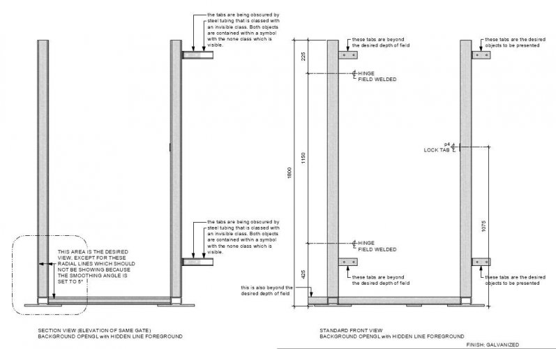
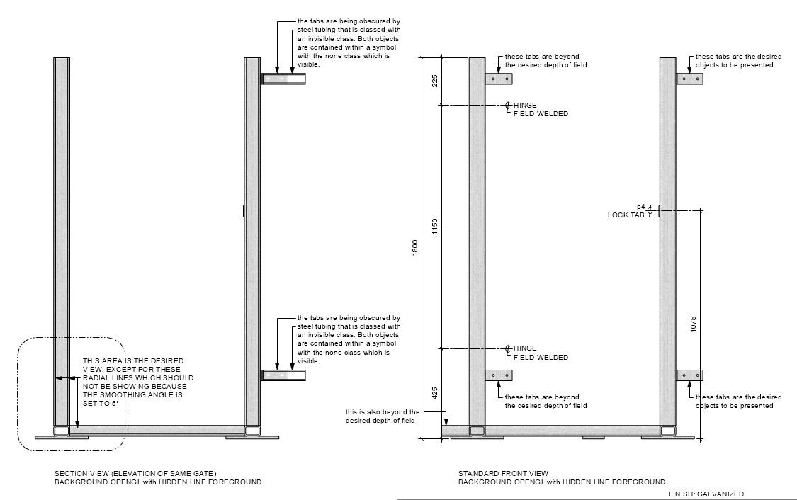
These are glitches that should eventually be addressed for section viewports.
1. Radial lines showing when smoothing angle should be preventing them.
2. Invisible objects being rendered when they are in visible symbols. Symbol contains two visible objects and the one invisible object. The invisible object is a 3D square tubing object with a class that sets its line weight and has been subject to solid subtraction to permit material use and then grouped to control visibility via class designation being applied to the group.
I was attempting to use the front view (on the right) but there is no means to restrict the depth of field to prevent objects in the background from being displayed. So I attempted to use a section viewport (on the left) to exclude objects that are further back in my model.
-
-
Does anyone know where the functionality for labeling centre lines with an overlapped C and L was moved to after deprecating the CL tool?
-
Issue: When dimensioning in the annotation space of view ports, the snap location to a hole's centre does not always appear.
This is most prevalent with extrudes, grouped objects and symbol objects but can occur in other situations.
On a design layer, create a rectangle centred upon 0,0. Place a copy in the clip board. Create four circles in various locations inside the rectangle.
Select rectangle and circles and clip surface. Extrude selected circles 8mm. Move punched rectangle to one side and extrude 6mm.
Paste in place original rectangle and extrude it 6mm. Lower extruded circles by 1mm below unpunched rectangle. Select both and subtract circles from rectangle.
On a sheet layer create a viewport to said design layer at say 1:4 scale to encompass both rectangles. Use a clip boundary. Now edit annotation and you should be able to place a dimension from any corner of the object to a centre of one or more of the circles. If not turn on the appropriate snap.
Next exit annotation change layer to design layer. Select both rectangles, duplicate and group. Move to one side.
Select both originals again, duplicate and create symbol. Move to one side.
Go back to the sheet and edit annotation. (adjust clip boundary first if necessary to see all six rectangles)
Attempt to dimension from any corner to any circle's centre. The centre snap points will not appear!
If you save and revert to saved you will probably be able to get the centre snap points to appear again but it will not be long before this functionality starts to fail again.
-
"Absolute positioning" is the method you appeared to be using to reset the accessory's location.
Your code was setting it to a coordinate location rather than directing it some distance from wherever it was currently located.
The latter being referred to as "relative positioning".
-
If the accessory is already at the absolute position 4.01 (and -16.08) it would not be moving anywhere new.
Display PosY before assigning it 4.01.
-
8 hours ago, hollister design Studio said:
Maybe call it 'scale preflight'...
I vote for "Modulus", the english language is without shame in grabbing words from other languages and reshaping the definition.
🙂ridere
-
Scale functionality sets the multiplication factor for the printable area in a Design Layer(s) in addition to annotation placed in those environments. No more manually sizing up or down text fonts (such as when used in AC's Model Space) to suit the final print output.
The plus of VWs is that a work file can contain more than one Design Layer with different scales and visibility whereas the last time I worked with AutoCad only one Model Space existed per file, excluding Xref functionality. A 3d model can be created at the centre of it's own environment without other 3d objects potentially being visible to one side or the other. Very flexible!
-
If deciding upon a Razer product your selection will need to be recognized by their synapse 2 software to work on the Mac.
When I received a new Death Adder to go with the new company issued PC I was going to let it go to the Jr Tech who was to work on my former Mac workstation and retain my old (dirty) DeathAdder for myself. But the Synapse 2 software required for the Mac could not find the new budget version of DeathAdder.
The large ergonomics of the Death Adder have been a big plus for me and assigning the thumb buttons to switch sheets/layers a feature that I could not imagine doing without anymore, whether it be on a PC or a Mac.
But I will say that one of the Naga's will be worth testing out, especially if you are considering operating from a PC. The placement of <CTRL> and <ALT> on most PC keyboards makes it next to impossible to use many frequent short-cuts with one hand without incurring repetitive stress injury from stretching one's fingers too far apart. One might (?) be able to assign some thumb buttons to act as modifier keys and definitely the <ESC> key. Every time you modify something in the Object Info Palette on a PC you need to press <ESC> or click in the main window before the other keyboard shortcuts become available. The menu system does not respond to changes while the object info palette is active. This behaviour might be limited to shortcuts where a modifier key is not required.
-
1
-
-
Unfortunately it would appear that the column tool does not place the centre mark into an annotation class.
I don't think any refinement of these structural tools has occurred since before 2013.
You can layout using 2d steel shapes and those PIO objects create thin dashed centre lines with a centre mark.
The embedded cross hairs cannot be rotated independently of the steel profile.
3d steel shapes do not give an option for cross hairs but you can always place your own to suit.
I have not loaded up VW2021 yet to see if their are any changes yet.
-
1
-
-
Class overrides via the Info Palette.
-
Something like this pool noodle arrangement?
Create a column from a circle of the desired diameter with the centre of the circle at location 0,0
and then extrude it to the desired length. Change your view to front or right side (use the keypad 2 or 6 respectively). Rotate the column from the 0,0 origin down to the desired angle. Change the 3d view back to plan view (keypad 5 or 0) and rotate the leaning tower in the desired direction. Finally move it into the desired 3d location. In the object illustrated I tilted and rotated four columns and then did a circular duplicate about the origin of 7 copies at 45 degrees. Did a solid addition to everything and finally created a hemisphere to act as a clip by intersecting the two objects.
What you see here is a view from below.

-
And there is even a good Vectorworks Youtube video, but I couldn't see how they aligned the cube for a true right angle cut through their staircase.
Our company is hopeful this can be used for quickly extracting accurate site measuring inside buildings.
-
I was also going to suggest looking into Pdf Pen Pro, partially because of the cost and my frustrating experience when trying to use Adobe's Acrobat Pro.
But alas I don't have that concern anymore, I was moved to a Win PC and have access to BlueBeam Revu again.
Now I have to deal with having to press "escape" or click the main drawing window after editing in nearly every palette before a keyboard shortcut works. Whereas before I could have simply pressed X or the particular short cut key on the Mac and the tool would become active.
-
How does one align the face of a ClipCube to a wall face for a true cut through a staircase in my instance. Of get it perpendicular to a plane of dots.
This is in reference to a point cloud's clip cube.
I know that the cube can be freely rotated about the cube's z-axis.
Thanks.
-
I think you need a holder for a mug of hot cocoa and maybe a heated back cushion.
A former co-worker used to place a shopping cart in all of his illustrations.
-
2
-
-
export 3d pdf
The result is a 3d model of an object that can be rotated about in a good pdf viewer for a fraction of the cost of installing Vectorworks.
BlueBeam can import your client's photograph but I'm not sure of its capabilities of merging 3d and 2d. You can get 30 day trials to functionally test it out.
But this is only an electronic version of what you had already proposed.

Multiple Extrude as "plugin-object"
in Vectorscript
Posted
A point object plugin would behave like the 3D W-Flange and 3d HSS objects in that there is no option to change the length and orientation by grabbing an end point with the mouse and dragging it to is new location. Whereas a line object has this functionality built into it by providing a start and end point for its length and behave like a line.
The rest of the functionality is adjusted through variables you declare to display in the Object Info Palette with the script using this data to create your object in a step by step fashion. Program coding. The coding options being Python or Pascal like as mention earlier. All the VW specific functions and procedures are listed within the Plug-in manager. You refer to the language guide for it's functions, formatting and procedures.