


bjoerka
-
Posts
453 -
Joined
-
Last visited
Content Type
Profiles
Forums
Events
Articles
Marionette
Store
Posts posted by bjoerka
-
-
I had the same today after updating to sp2 with 2024.
I did a repair from the vwx updater and after that it does not seem to appear...
-
 1
1
-
-
As long as the realtime engines accept ies files and do a correct interpretation - that would be the best.
In our office we do a lot with UE for visualization (except me .-)) and they often use ies files (to my advice) and the results are fast and quality vice ok.
But if the source program is not able to handle lights correct then, i think, also tw will not represent the correct result...
-
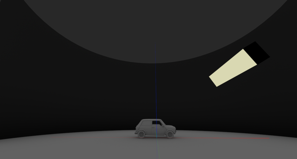
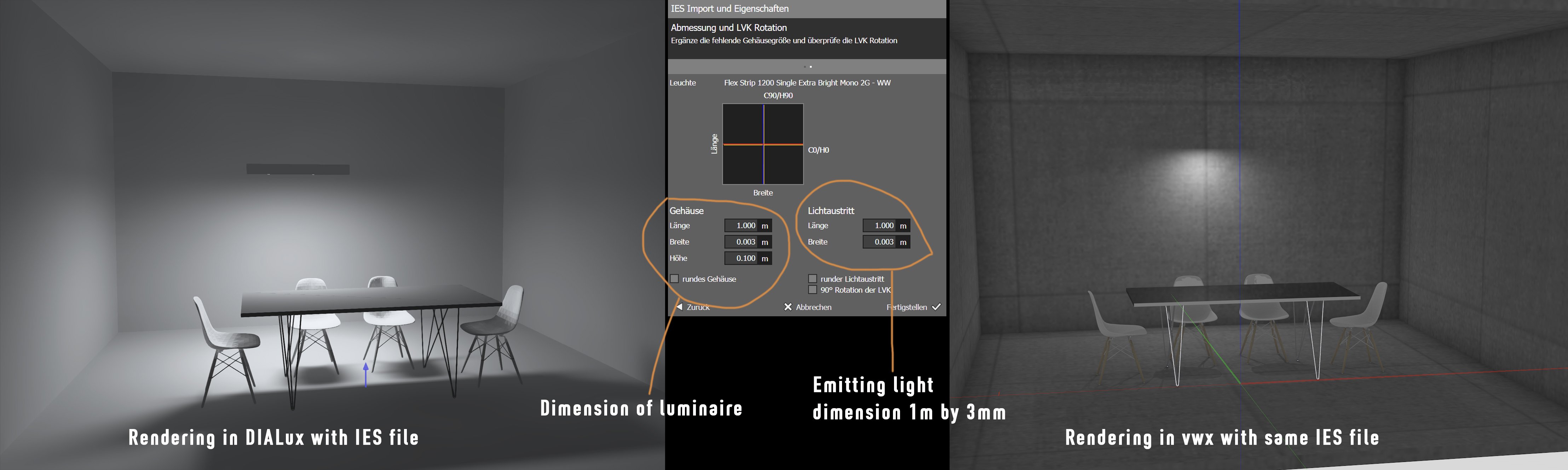
It seems that the interpretation of some IES files is not working correct.
As to be seen in the example, i used an IES file for an LED striplight, that is defined to represent a luminaire with the length of 1m.
Vectorworks does not recognize this information and the light distribution is shown as a single light emitting point instead of a linear source.
Comparison is done in the actual version of DIALux.

-
1
-
-
I think the render time is ok.
But i really like line & area light because they are easy to setup compared to addintional geometry that has to modeled to apply a texture to it.
And often, to get the correct light power out of them, these textures get washed out...
It´s a bit of struggle to find the best and most effective way...
I posted something similar in this topic -> light combination
-
Sadly the visualization palette hasn´t got any improvements with the update 2.
Furthermore i see something that did not happen with update 1.1
I have 2 files open. The first has got three lights, one named area light. The other are named Light-1 / Light-2
When i open a second file the visualization palette is still showing the lights of the first file...
Switching Light-1 and Light-2 on and off works (even they are from the first file) but an error message shows up, that some lights could not be selected...
Weird...
-
1
-
-
Same here. It´s working with 2024.
Works like a charm...
-
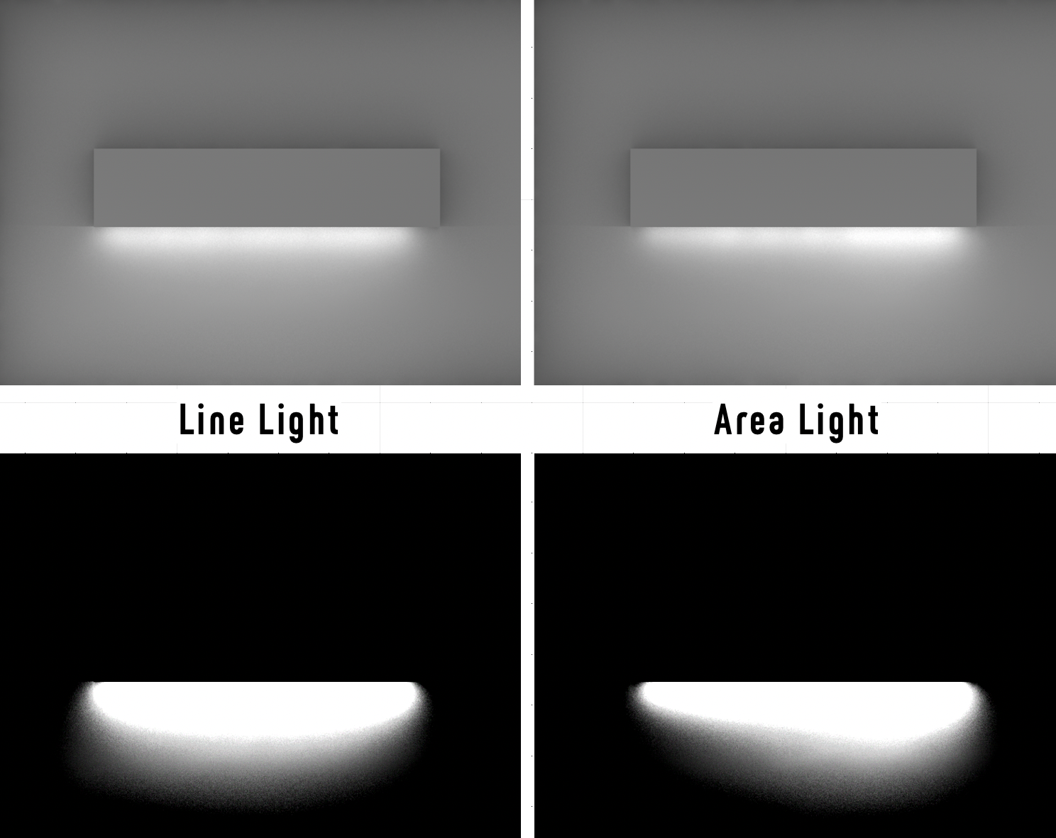
I was playing with lighting, trying to simulate led stripe similar lights.
I used a small area light and saw in an elevation, that the light distribution is unequal compared to the geometry.
The aera light was generated from a rectangle, 2000mm by 10mm.
I compared this to a line light, which has an equal light ditribution.
Maybe a very specific case, but not as expected.
See the screenshots below.
Upper images rendered in vwx. Lower ones "tuned" in ps to show the lightdistribution.

-
2
-
-
Break the modeling down to many as possible symbols, so you can fast change dimensions, fillets etc on repetative elements .-)
-
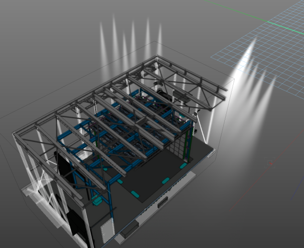
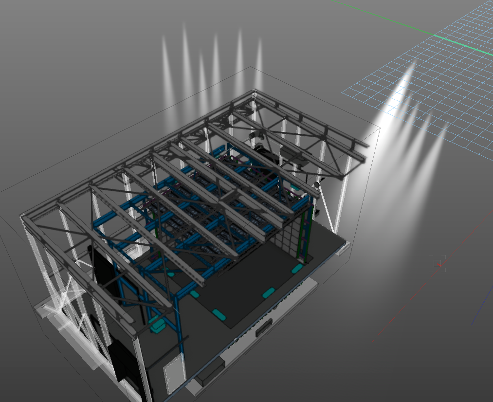
Is this the correct behaviour that lighst outside a clipcube are rendered when in shaded view?
The drawn lights are from lighting instruments...
-
On Mac, there was a small update 1.1. If available for Windows...
Did you apply this?
Also try to use the repair function within the vectorworks updater application.
Sometimes that fixes misterious things...
On my Mac i have very less random crashes... Maybe 2-3 a week... But not replicapable...
-
it´s working again after a reinstall...
-
ok. thanks tom. we don´t see this on machines that have update 1.0
but after a crash a few minutes ago vectorworks won´t start. it´s stuck with the final initilization
maybe that has somehting to do with the failed operations in the updater
i´ll do a re-install .-(
-
it seems that the X-ray selection in update1.1 is broken.
everytime i hit the b-key the x-ray can be seen, but as soon as i move my mouse it disappers.
i tried a repair from the vectorworks updater, but the updater always fail on a file "-_NaN.zip"
also the function to ga back to update 1.0 fails at exact that point...
is both a known issue?
-
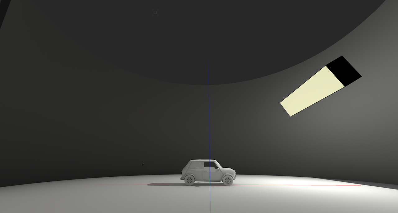
Did you try to generate the area light with only a 3d polygon?
Looks as if your area light is made from an extrude object...
-
Maybe use a combination of a backlit texture or a glowing texture and an area light.
I just did a quick test with one hollow box, a thin extrude with a transparent texture in front and an area light inside the box.
May this is a way to achieve what you are looking for when you separate the texture and the light to get better control about the look.
1st image with only glowing surface, 2nd with area light inside the box.

-
1
-
-
I have to exchange a network switch to another model with more sockets .-)
But my block schematic is nearly finished and all sockets on my 24-port switch are connected to their destinations.
What is the best workaround to replace the switch in my drawing with another that will have 48-ports without re-connecting all existing connections?
I tried to place a new one and drag it to the existing connections but that does not connect the wires...
Any help is much appreciated .-)
-
Hi Conrad, yes, you described it correct.
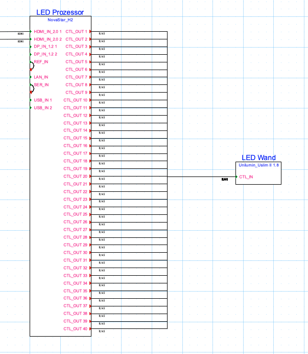
Just to describe my intention behind the multiconnect.
The LED processor has got 40 outputs in the device description. If i want to connect every single output to its destination, then i have to place every single led module so that the output gets connected to its corresponding led destination. In my understanding this is more like a detailed cabling plan for the supplier, so it doesn´t have to be a part of the block schematic.
So the single device, which i called "LED Wand (wall)" represents a bunch of led tiles.
Maybe it is an option inside the device builder to build a connection that sums up a number of destinations with a checkmark or pop-up window.
just my thoughts .-)
best.
bjoern
-
Thanks Nikolay for reporting.
I was happy yesterday not to save the file after generating the equipment .-)
-
1
-
-
Thank you Nikolay.
I´ll give that a try!
-
Hi Nikolay.
Thanks for the reply. I sent you the file that i am working on.
-
Helpfull might be an option in the preferences to scale the dragger to my own size.
-
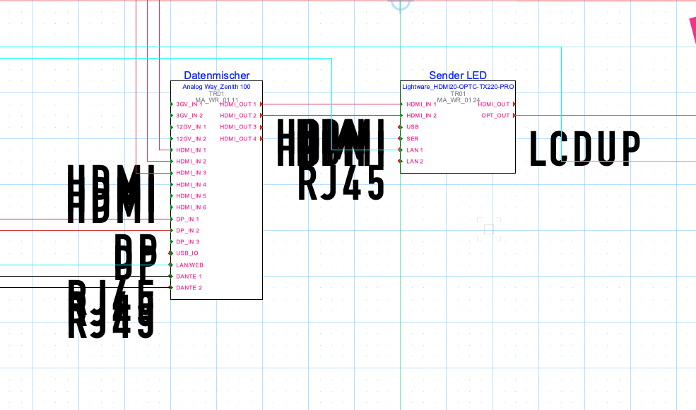
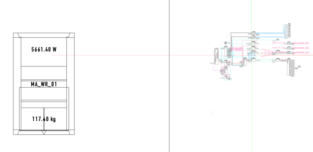
I have two layers in my drawing.
The first for schematic drawing set to scale 1:1 and the second for 3d rack elevation, scale set to 1:10.
When i deactivate the option "Ignore layer with different scale" and generate the equipment on the layer with the scale set to 1:10, all fonts for the connections between the devices are scaled.
Anyone else seen this before?
schematic before generating equipment
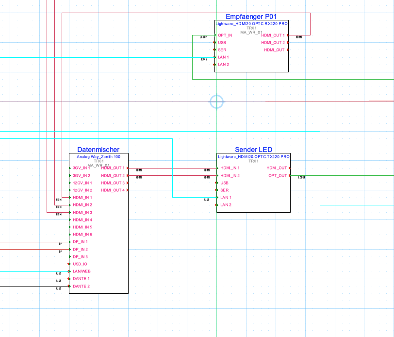
schematic after generating equipment
-
Is there a way to draw automatically multiple connections to one single device that represents 60 single devices drawn as one single?
In my case these are the connections from a led display controller with 40 control points to his destinations.
Multiple connections drawn with the connect tool starts with all signal starting point but drops off a single connection...
This is what i want to achive without drawing 40 connections .-)
-
I didn´t reply for the last time - too many other things i have been working on ,.)
Thanks everybody for their input and inspirations!
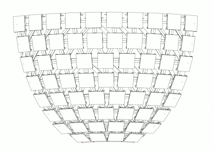
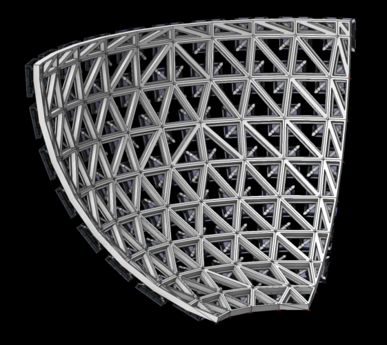
We have done some work in Rhino and in vwx with grasshopper and marionette, but finally the job was done the traditional way .-)
cutting the 8th of a sphere in vertical by defined dimensions. curves extracted to duplicate 3d loci on these and then placing 3d symbols on the locus.
after the first design step the sub-construction was modeled with 3d polys, thickend, holes cut, plans drawn.
now it´s part of the structural engineer .-)
attached some screenshots of the (hopefully) final design...
-
4
-


Navigation palette fails to refresh when switching between files
in Troubleshooting
Posted · Edited by bjoerka
no, i don´t think so. viz palette does not to seem work better after repairing files. event though they stated it has been fixed with sp2 -.)