


bjoerka
-
Posts
453 -
Joined
-
Last visited
Content Type
Profiles
Forums
Events
Articles
Marionette
Store
Posts posted by bjoerka
-
-
Tried this and quarz was enabled through all the tests.
Disabling does not change the problem.
The font gets scrambled with the publish command.
-
OK. Please pull it to the wishlist ;-)
-
They both work correct.
-
Hi Jim,
any news about this topic?
thx.
Bj?rn
-
I have encountered a strange behaviour between the visibility of classes for design layers and the setting of classes in viewports. seems that the visbility of global classes affects the visbility of geometry inside viewports, overriding the viewport settings.
not so easy to explain. therefore i did a screenrecording.
anyone got the same behaviour?
-
Hi,
i am not the super coder, but did the following script to give our team some lines to set the font and size to predefinded sets.
It works so far when it operates on normal text objects and if no object/text is selected it sets the defaults to start with the text tool.
What it does not is to operate on a callout text....
Any hints how i can solve this?
Thanks.
Bj?rn
---
PROCEDURE JNCorpoA;
PROCEDURE SetzeGlobal; {Standard for no object selected, text tool activated}
Begin
NameClass('None');
TextFont(-29760);
TextJust(1);
TextSize(6);
TextSpace(2);
TextFace([]);
TextSpace(1);
SetTool(5);
END; {Procedure SetzeGlobal}
{------------------------------}
PROCEDURE SetJNFont;
{ Change the Font of every selected text object in a layer to jangled corporate A }
{ November 2013 Bj?rn Kantereit}
CONST
jnFont = 'jangled corporate A';
VAR
H :Handle;
{JNF :Integer;}
function Set_JN_A(H :Handle) :Boolean;
Var
JNF :Integer;
Begin
SetTextFont(H, 0, len(GetText(H)), -29760);
SetTextSize(H, 0, len(GetText(H)), 6);
End; { End Procedure SetJNFont}
BEGIN
{JNF := GetFontID(jnFont);} { new Font ID }
ForEachObjectInLayer(Set_JN_A, 2, 0, 0); { All objects, selected only, current layers }
END; {Procedure SetJNFont}
{-------------------------------}
BEGIN {Procedure JNCorpoA}
IF FSActLayer=NIL THEN
SetzeGlobal
ELSE SetJNFont
END;
Run(JNCorpoA);
-
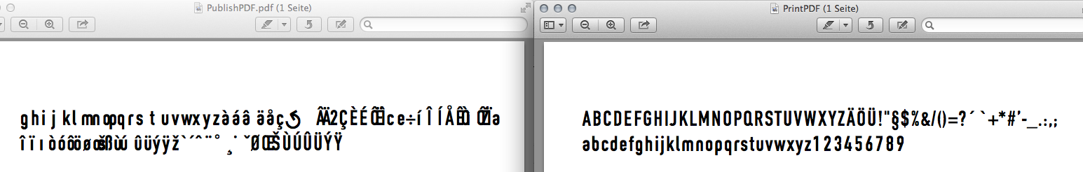
Here are two pdf?s.
One generated with the publish command, the other one with print and save as pdf...
What is weired is that when you open the pdf generated by the publish command with Acrobat Pro everything is fine. Opening it with preview it gets scrambled...
Tested this with other applications to check if it belongs to the font and there everything is fine (Pages, Numbers, InDesign, Illustrator, Word, Vectorworks 2011)
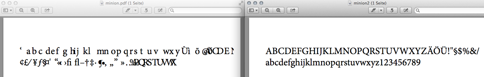
Also tested this with another font. Minion.
Left side shows the result with publish command, right side with print-> save as pdf.
-
I had the same today.
We use an OpenTypeFont, built for our office.
When i use the publish command, the text gets scrambled when i open the pdf with the preview app. Opening the same pdf with acrobat pro shows the font as it shall be.
Doing the pdf again via the print dialog and choosing open with preview shows everything is ok...
Sounds weird but happened...
Is vw using different routines to generate pdf?s?
-
Is your drawing very detailed?
Did you try this with a drawing that only has a few objects?
I see this too when i write PDF?s from very huge and detailed drawings.
Especially many hatches slow down the screenredraw in PDF?s.
But i think that this isn?t rather a vw issue as everything inside the PDF are vector elements...
-
I have been testing a few more from different creators and the behaviour ist still the same.
After importing (not referenced) and activating an element, the info palette is greyed out.
I?ll zip some of the files and send it to you directly.
Best,
Bj?rn
-
Top. Thank you!
-
Ok.
I just sent you the file that i was working with.
-

so let?s hear what Jim says about it...
-
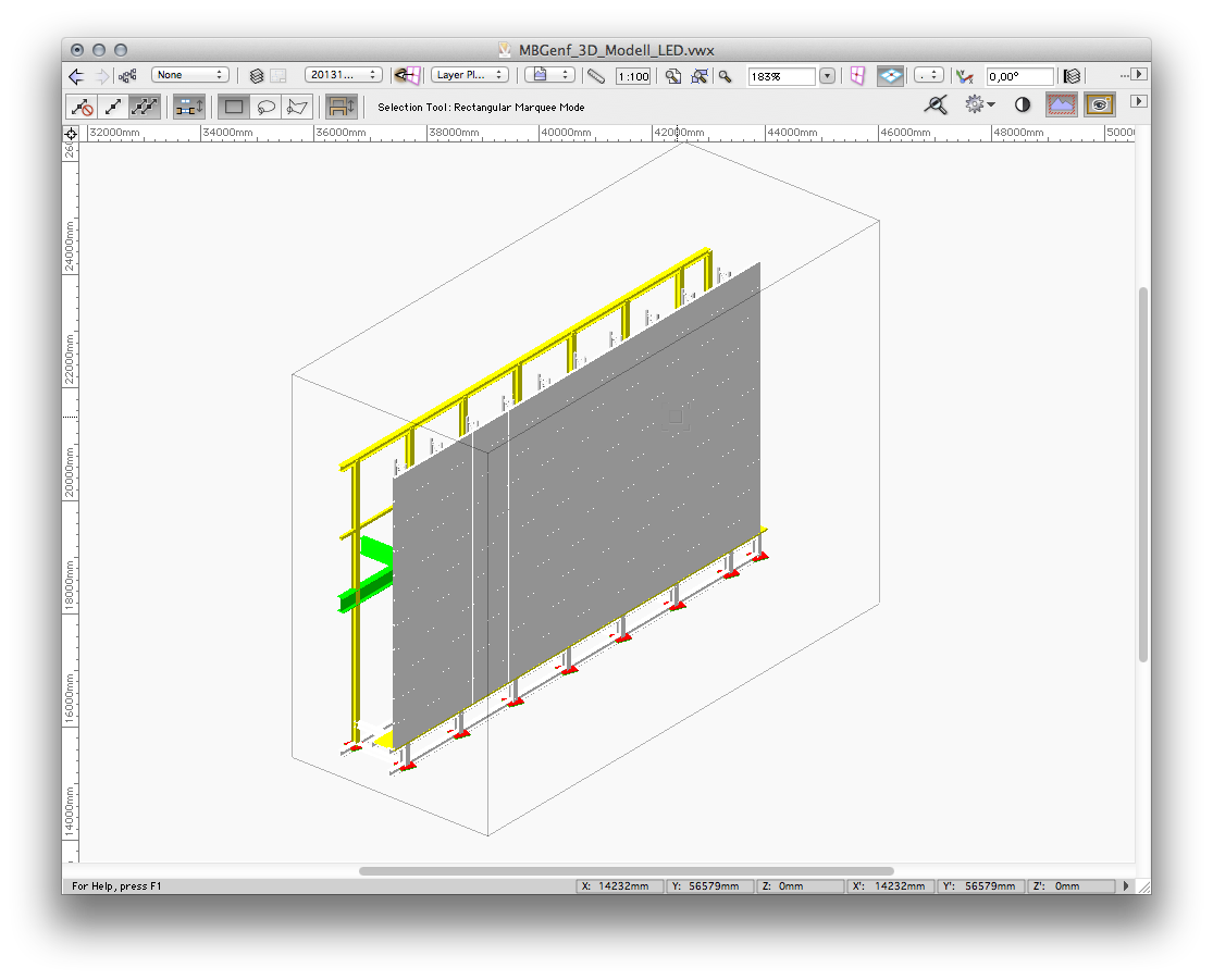
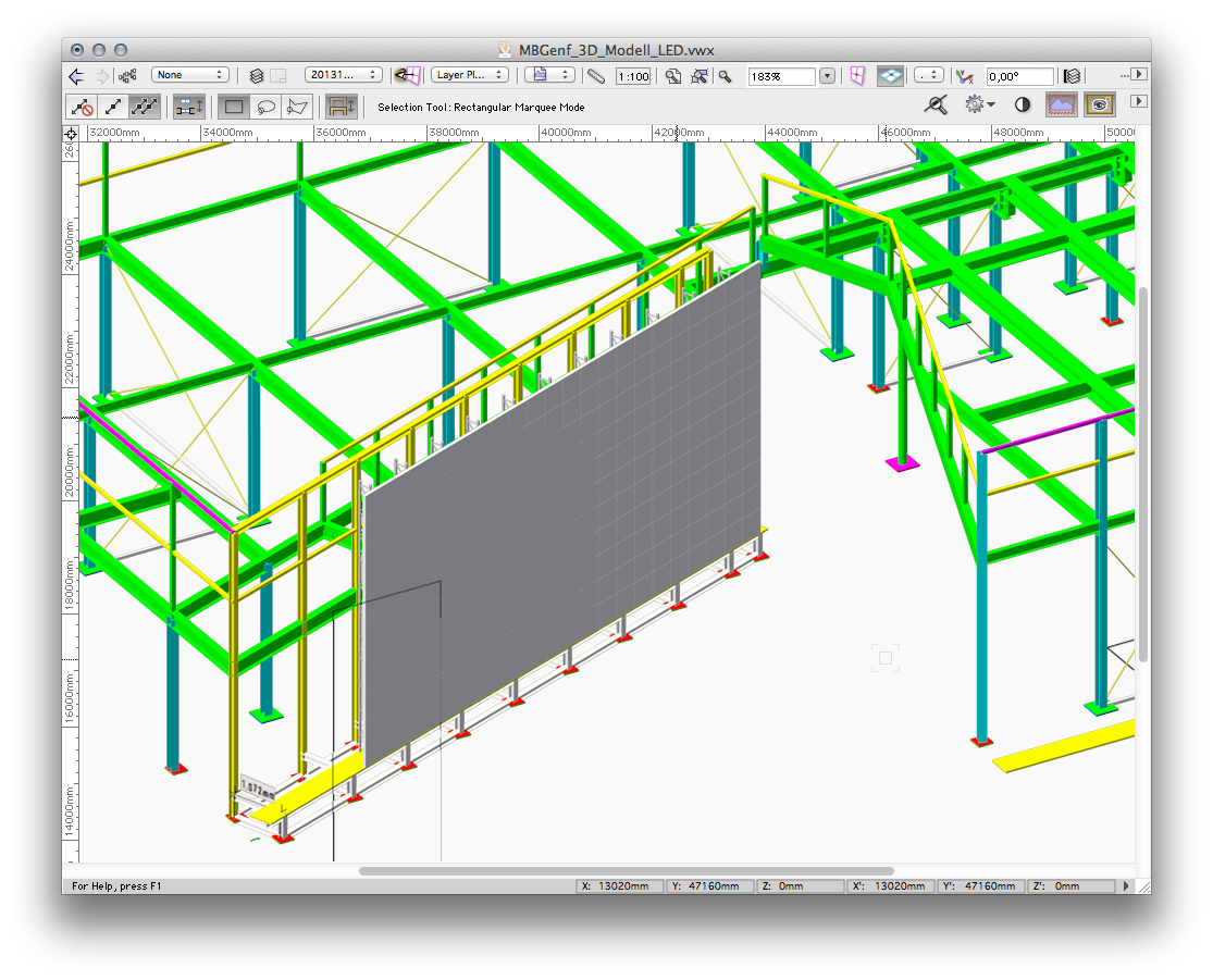
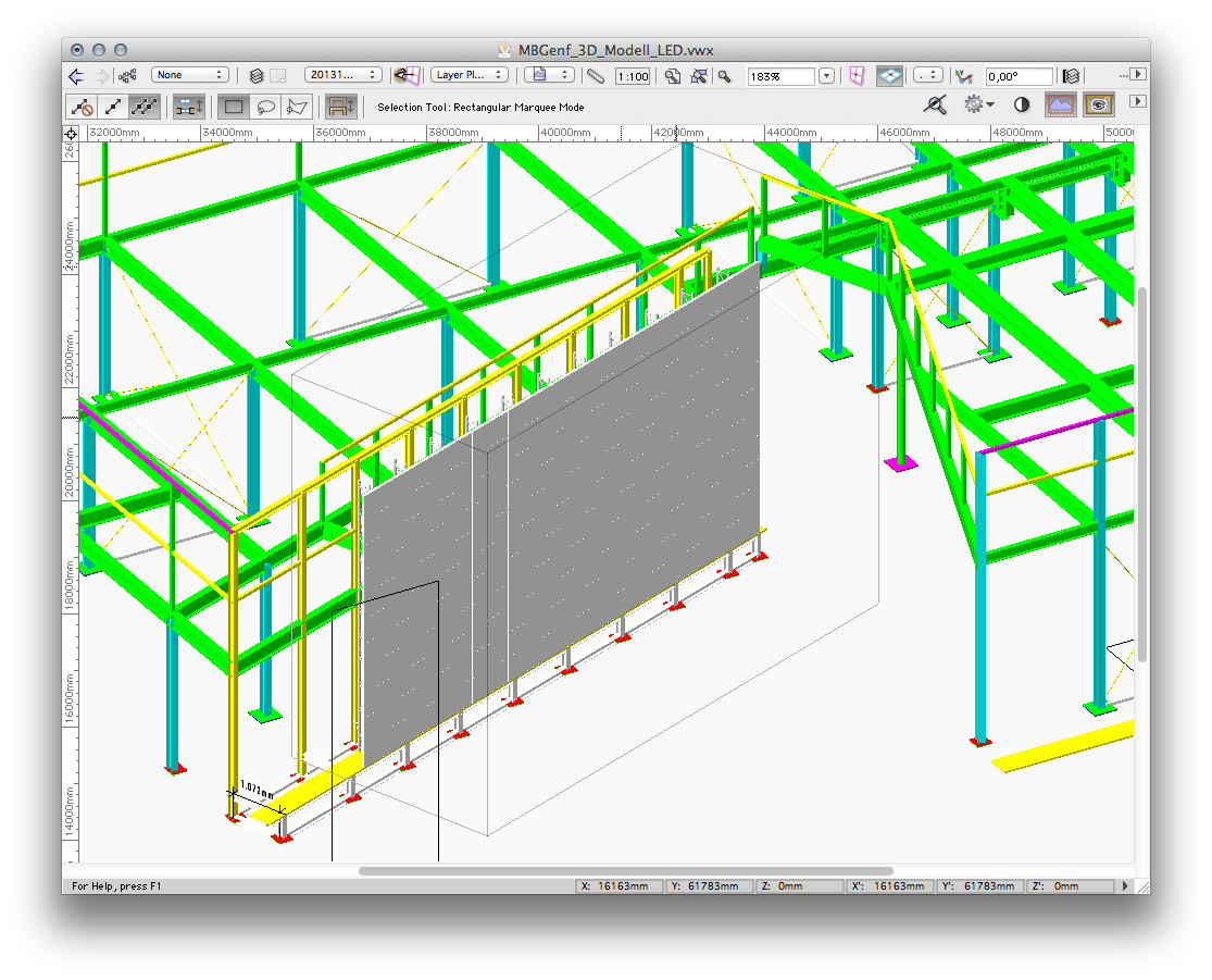
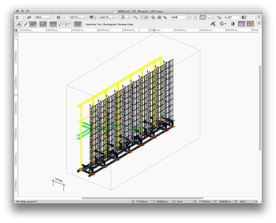
Not sure if this is working like it should.Take a 3d model and turn on "view - clip cube", rendering set to open-gl.Everything seems fine.Switch to "view - rendering - any renderworks"Now the clip cube is ignored and the whole model is visible. At this point i am not sure if this is correct or clip cube only works on wireframe and open-gl.Now switch back to open-gl. The bounding box of the clip cube is displayed in light grey, but the whole model is rendered and visible.Turning the view with the flyover tool does not change anything.Switch back to wireframe and now only the inside area of the clip cube is displayed like suggested.Feature or bug? .-)Best,bjoernclip cube with open-gl [img:left]http://www.kantereit.de/vw/cc-opengl1.png[/img]
clip cube with renderworks [img:left]http://www.kantereit.de/vw/cc-renderworks.png[/img]
clip cube with open-gl again [img:left]http://www.kantereit.de/vw/cc-opengl2.png[/img]
clip cube with wireframe [img:left]http://www.kantereit.de/vw/cc-wireframe.png[/img]
-
Could you send me such a file so that I can experiment a bit? I may be able to find a better/faster solution.
tech@vectorworks.net or you can post it here if it isn't sensitive info.
I can send you one. Its about 20mb. I?ll describe it in the email.
-
we are currently only referencing dwg?s. when we import dwg?s we do it like you said - intoa new fresh document.
but anyway - as we updated our vw2011 versions to vw2014 we have a lot of drawings where non standard vectorworks dash styles are inside. and we have to work with these drawings.
some people here did not follow the rules how to import and clean a document after imprting dwg files. so we are carrying many dash styles from one drawing to another by copy paste and so on.
As you suggested with referencing and importing geometry it is not like you described. After copying or deleting a reference (keeping the drawing in my file) i also import the dash styles that are defined in the non worling document.
in vw2011 it was easy to clean up non vectorworks dash styles like i described above.
no way to do it in vw2014 in a similar way?
hope you understand what i mean...
-
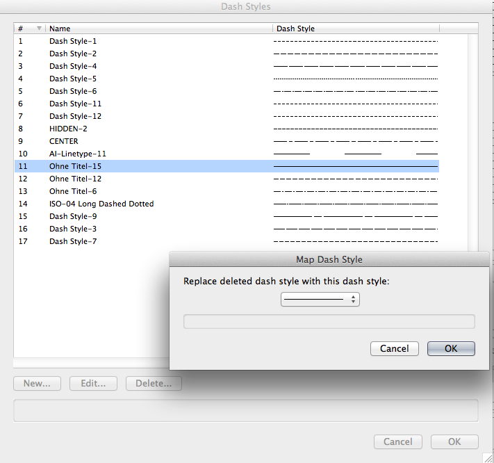
It?s the line types .-)
In VW2011 it?s called dash styles. So my fault using the wrong name .-)
In the screenshot you can see what i was referring too.
[img:left]http://www.kantereit.de/vw/dashstyle.png[/img]
-
In most cases i try to avoid importing geometry from other consultants directly into my daily files.
What we did prior to VW2014 was to import data into a fresh vw document, clean the drawing to what was needed (deleting linetypes, unused symbols...) and the referenced these into the actual file.
What i like (now) with vw2014 is that you can directly reference dwg files without all this extra work for cleaning. After referencing (and of course caching the dwg file) you have full control for the visibility of layers and classes via the info palette as the referenced files are handled like viewport.
What is not working for me is "refreshing" referenced dwg files without some extra work. I tried to update a referenced file via the edit option in the organize settings and after chosing the newer dwg file the drawing is stripped down to a little red cross in the drawing. So you have to activate this and edit the layer and class visibilities to get everything back.
Hope that helps a bit.
Bj?rn
-
I trying to find out how i can replace "wrong" line types that are imported from dwg files or other vw versions but can not find a solution except using Custom Selection.
In VW2011 (which we used until 3 weeks) it was possible to edit the line types and while deleting one i was prompted to choose another one for replacement.
In VW2014 line types that are used can be deletes in the resource palette and are automatically replaced by a continous one.
Do i miss a tool?
Thanks for any help.
Bj?rn
-
Hi Jim.
I?ll try a few more files and respond what?s happening.
Best,
Bj?rn
-
Hi,
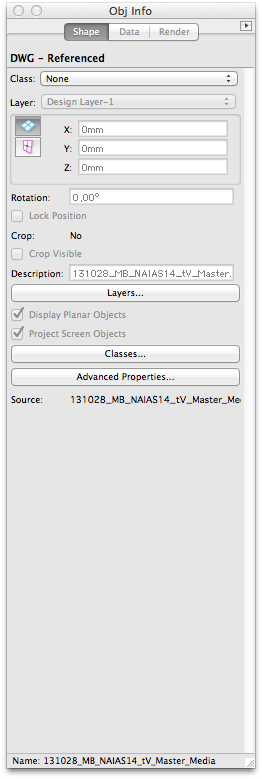
as the topic says - the Info palette is not working directly after importing a dwg file as a referenced file.
The buttons for advanced properties layer and classes are not responding. Some parts of the info palette are grayed out...
Closing the info palette and reopening solves the problem. Also clicking with the right mouse button on the drawing and choosing "edit properties" brings the info palette back to work.
Is that a known issue?
I tried this with several dwg files...
VW2014 SP1 Mac OS 10.8.5
screenshot of the info palette...
-
Thanks guys.
I allready found out that there mightbe a way to change the default setting with the Plug-in Manager. But at the moment changing values inside the "drawing border" plug-in doesn?t do what i suggested.
So i guess the best suitable way at the moment is to use the method using symbols to be inserted as plugin objects.
I didn?t think about that :-)
What i like with the "drawing border" plug-in is that the size of the border adapts itself to the suggested paper size. We often use customized sheet sizes that exceed the length of a DIN A0 drawing .-)
Maybe someone of the NNA team can drop in the discussion and show a solution to change the border settings to other default values.
-
Hi,
i am looking for a way to change the default values that are inside the sheet border setting (Border settings button in the info palette)
The default values are set to 20 for the borders and i want that to change permanently to 5 and have the grid zones values change to 0 permanently.
For some of the tool (screws windows) there can be .txt files found inside the vectorworks application folder where settings for default or pop-up entries are stored. But i couldn?t find anything refering to the sheet border tool.
Any suggestion how i can solve this?
We are currently using VW14 with SP1.
The idea behind is to standarize as many as possible as we are working with about 22 licences.
Thanks for any help.
Bj?rn
-
hi there,
does anybody know a solution how i can put a textfield with x=... / y=... / z=... with a click on a geometry or 3d locus and the coordinates of this point are drawn into the textfield?
best.
bjoern
Scrambled Text in pdf Export
in General Discussion
Posted · Edited by bjoerka
We have an own font that was built for our office. It is very similar to the Gravur font. And as it is our housefont we have to use it.
If you want it for internal testing for the future i can send it to you.
The other that i used for the test was Minion, but it also occurs with Gravura and Akzidenz Grotesk.