


scottmoore
-
Posts
673 -
Joined
-
Last visited
Content Type
Profiles
Forums
Events
Articles
Marionette
Store
Posts posted by scottmoore
-
-
Check out the VWX tab in the edgelightrgb.com site.
Shameless plug.
-
 2
2
-
-
Just now, Graeme Smith said:
@scottmoore Thank you so much
You are welcome. Let me know how that works for you.
-
I have no idea if this will work, but you can try it. There is one function that fires a script that has been converted to a tool which was written by Andy Dunning of Landru Designs, therefore, I cannot give that away. It toggles your file from feet/inches to meters. VERY handy. You can ask him directly for the script if you like.
Otherwise, these all fire quick key commands which means you will have to modify your workspace to garner many of the remaining key functionalities. There should be two pages of commands.
PAGE 1:
Duplicate Array / Align-Distribute / Scale Objects / Layer toggle set 1 / Layer toggle set 2
Number instruments / Replace Symbol / Rotate / Connect-Combine / Trim
Return to home screen / Imperial-Metric (NA) / Render Bimap / Create viewport / toggle to second page
PAGE 2:
Return to page 1 / Export Image file / Import image file / Export DWG / Import DWG
Create Symbol / Label Legend Manager / Lock-unlock (toggle) / Export Worksheet / Page Setup (printing)
Sweep / Extrude Along Path / Multiple Extrude / Taper Extrude / Set lighting options
Hopefully this will prove helpful to someone. If nothing else, perhaps it will give users some additional ideas on what to do with a StreamDeck. I find it to be an amazing time saver.
-
On 8/18/2020 at 12:50 PM, Graeme Smith said:
@scottmoore If you could share it that would be amazing
I’ll see if I can figure that out tomorrow.
-
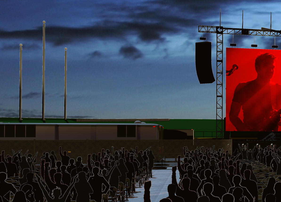
I finished a new set of audience image props and starting with vector based artwork and create the image props with alpha transparencies makes all the difference. Much improved.
-
1
-
-
Pat, I had forgotten about that thread! Thanks for the insight!
-
They are image props. The record idea is interesting, but I am always hesitant to add any complexity to the drawing that might not be necessary to keep the drawing efficient. Also, you definitely want to randomize your props which might be problematic with the seating tool. Of course I guess you could lay out a symbol instance and then randomly select and replace.
-
1
-
-
17 hours ago, TomWhiteLight said:
Funny you should mention that and thanks for the compliment. They are but created from readily available images online. The funny part is I’ve been using those for years and starting this afternoon I am making a new set that should be much better. Got a couple of ideas I want to try out.
-
My guess is the little crosses is the loci created by BraceWorks. Locate the class associated with the loci to turn it off. I don’t recall what the class is called.
-
27 minutes ago, Andy Broomell said:
I'm pretty sure it's a bug with regular image backgrounds. The anti-aliasing artifacts shouldn't appear with Panoramic/HDRI backgrounds.
What type of background is being used in your image, @scottmoore?
That did seem to be the issue. rDesign and Andy, thanks for your input. I think I can make this work with a stock HDRI background. Eventually I need to learn how to make one myself, but that is probably a job for future me.
Thanks guys!
-
1
-
-
It is a regular image assigned as a panorama.
-
I am working on rendering an outdoor project (perhaps a bit optimistic in the age of COVID-19) and am using a panorama as a background. The RenderWorks camera and the sheet layer viewport are both set at 600dpi. Rendering is in Final Quality so that we are all on the same page. The issue is the transition between the panorama and the model. I am getting a lot of artifacts. I originally rendered this at 300dpi with the same issue. Any suggestions? Hoping this is something simple I can sort out.

-
On 8/6/2020 at 10:06 AM, Graeme Smith said:
@scottmoore Hi,
Would you be willing to share your profile for this, I'm struggling to create the more complicated things that don't have shortcuts.
Thanks
Mine are all based on shortcuts. There are a couple of scripts that I converted to tools to which I then added shortcuts. I don’t entirely recall the process for this as I’ve only done it once.
I am more than happy to share my profile. I’d have to figure out how to do that though. 🙂
-
35 minutes ago, Wesley Burrows said:
This arena in particular was sort of a pain because it was originally constructed in the 1930's and has been renovated several times, so the DWGs, and in some cases the hand-drawn original section drawings, did not agree with each other. Reconciling them in to agreement was an interesting mind exercise. It took a lot of help from the site survey notes, dimensions and a bunch of pictures. In any case, after you have a solid frame work, it really comes down to time and how much detail you want to put in to it. I think that Arena as shown above took about a week to model. I used everything from extrude along a path, loft surfaces, nurbs, simple extrudes, add/subtract solids, extract tool, to the projection tool and more. It takes a fair amount of familiarity with the 3D modeling tools available to figure out what might be best to use for a particular task. Eventually you start looking at real world objects and think about what tools you'd use to model them in real time, it's a sickness.
But generally speaking I work from the arena floor outward and upward. It really helps to have section views for elevations, but those aren't always available for some spaces so, I also rely on site survey notes, and in some cases photos with some educated guesses based on typical dimensions of different construction materials/doors etc.
But for a few hints, you can take a section view of a lower bowl of the arena, draw a simplified version of it (basically like you're looking at a set of stairs from the side) and extrude that along the path of the arena floor. Some arena's don't have a lower tier that is the same the whole way around, so you could do a series of the above, for each different section. I've also used the loft surface tool to create the different tiered bowls. Every time I do it it's a little different, and every time you learn different ways of doing stuff. There really isn't a right/wrong way, it's what works for you. You kinda just gotta go for it any not be afraid to make mistakes and learn.
I know that's not exactly what you asked, but I hope it helps.
Wesley,
That is a pretty spot-on analysis of how to draw venues. I will add that taking some extra time to turn items into hybrid symbols is pretty much always worth the time. Consideration of classing, class line weight, pen color, fill color and textures can be huge time savers; especially when you decide to change something later on.
-
23 hours ago, SCParker said:
Hi Ryan,
I happen to be in the middle of making a series of how-to videos on just this topic. Here's a rough edit covering exactly this. I'll be posting the series soon.
hth, Scott
Scott,
Thanks for the detailed walk-through. Very helpful. I've never really used the seating tool so I decided I should at least figure it out after watching your video. I do have a question and a comment.
• It appears the "nudging" a seating section causes it to lose its numbering. All seats become number 1. That does not happen if you move a section by a prescribed distance. Does that seem to be the case for you?
• It is a bit of a drag that you cannot modify multiple sections at once. For instance, if one forgets to use classes, and wants to go back and add that functionality, you have to do it one section at a time.
Regardless, thank you very much for the time and effort you put into that.
-
1
-
-
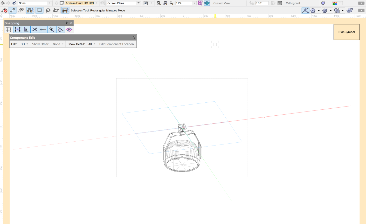
On 6/30/2020 at 10:33 AM, Daniel Dickman said:
Along the lines of editing 3D symbols... When editing the 3D component of a hybrid symbol, I've recently noticed that I can not select a 3D view from the drop down. Flyover works fine but the 3D view drop down is grayed out. Any ideas? What am I missing here?

That is not expected behavior. Not sure what would cause that.
-
2
-
-
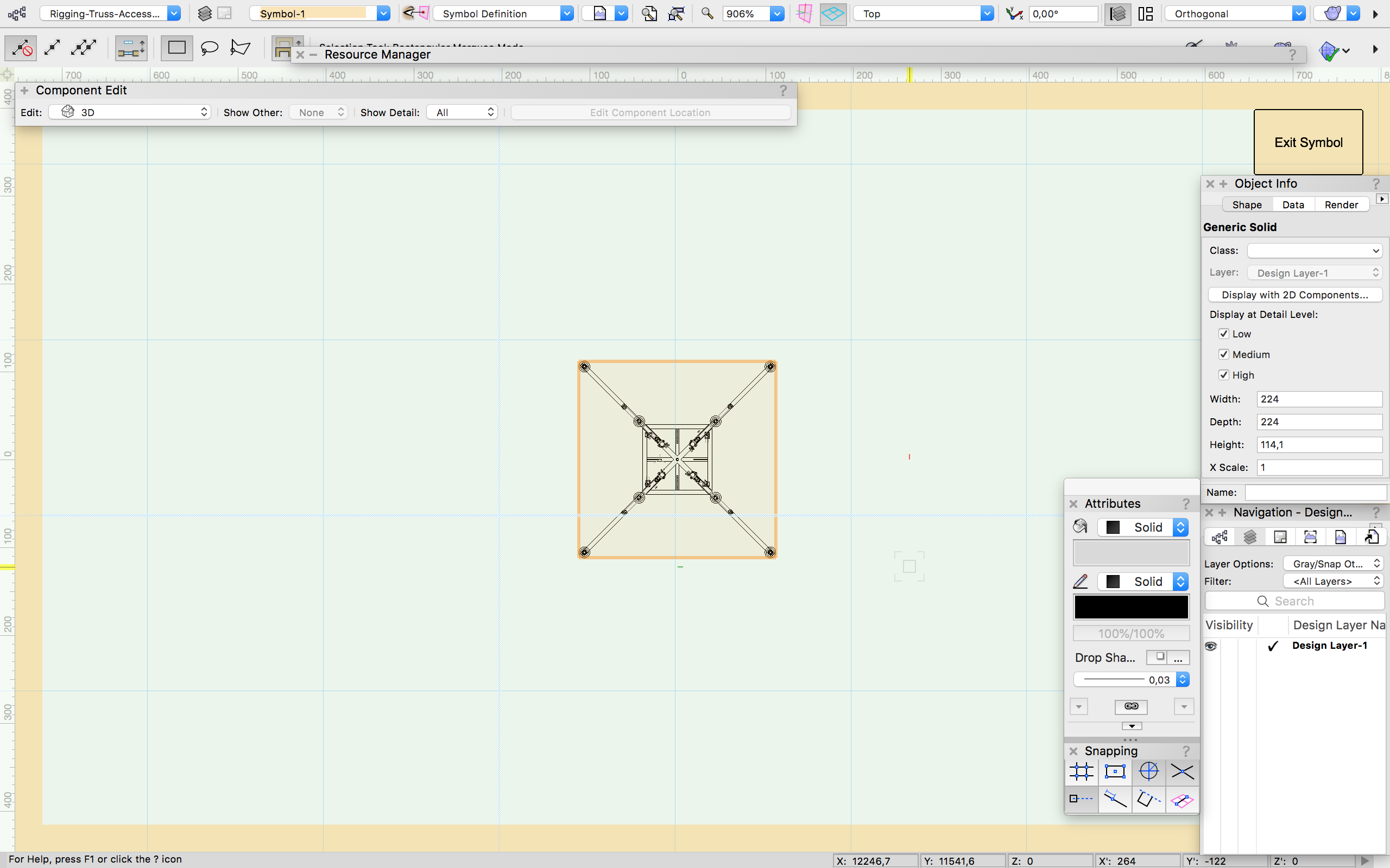
On 7/16/2020 at 9:11 AM, Safak Sari said:
Hi everyone. I need some your help. I'm trying to improve my spotlight experience. But i got a problem. I want to change 3d objects of truss outrigger.Rather than i want to cancel 2 pieces of brace or outrigger. I can't get in the model as this photo. Where i may get a problem. Please inform me.
Thank you
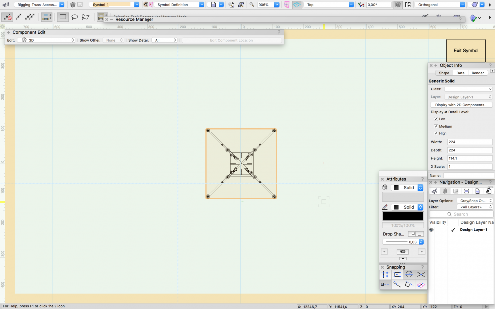
This appears to be a generic solid which offers no real editing options. Unless someone has a better idea, you will have to redraw the elements.
-
1
-
-
Just throwing out that I am seeing the same thing.
Thanks for the script! It is a serious time saver!
-
1
-
-
I just build them at various tilt angles and insert the symbols I need. Then it’s just a question of rotating the hybrid symbol in plan view to give me what I want. For most renderings it seems fixtures seem to end up in straight and/or fan focuses so this works pretty well and I don’t have to waste any time on focus positions.
-
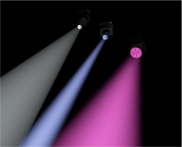
I've abandoned using Spotlight symbols for rendering for this reason. I developed a series of simple lighting symbols I use for this purpose that solve the beam origination issue. Still doesn't solve the fall-off issue, but better than nothing and definitely speed up the period of time it takes to get renderings together. Here is an image of a generic profile, a "sharpy" type fixture and a "Bee-Eye" type fixture to give you an idea.
-
1
-
-
On 5/6/2020 at 2:46 PM, awlightingdesigns said:
Thanks everyone for trying to help figure this out. At the time of my last post I pretty much gave up on it exporting correctly as .3ds because of the long standing issues with how Vectorworks handles this process. Maybe someday they will fix it so it works correctly. I have spent the last few months learning more workflow in vwx and using the software for what it was intended. I have found enough work around for now getting my work into 3D as I do a lot of previs. Mainly if an item has a simple 3D option this seems to export ok most of the time. Otherwise I will convert it to mesh and simplify larger meshes. I hope someday this works like it should this adds a lot of time to the workflow. I have to save a separate "converted" file because once you mesh things you can no longer work with them the same way you could when they were objects. Then if I need to make changes it is back to the original, make the change, and then you have to start meshing again- this can take a lot of time depending on the number of objects. I have started learning more in Blender and will try to figure out changing the normals in there. @Ryan Lilly If you have any idea of what to check in Blender or think of where to check/change the normals let me know.
Have a good one and I hope everyone is staying healthy and safe during these times.
My days of exporting into visualizers is pretty much over so I may not be much help, however, I do have a suggestion. The Plug-in tools developed for VWX can be time savers, but can also cause issues as they were designed specifically to be used inside VWX before there was much concern for exporting into anything other than a DWG file. For the purposes of exporting and real-time rendering, you may be better served with direct modeling. Even the most complicated staging surfaces can be created with two simple pieces of geometry: a deck and a face. Working this way avoids any need to understand how the PIO tools are built, allows you complete control over number of vertices, complete control over how textures are created and applied and can be faster overall. Just a suggestion.
a few years ago when we were exporting into MA3D, my team always talked about converting items to generic solids to avoid issues.
Perhaps this can help?
-
4 hours ago, Pat Stanford said:
I believe the change was implements so that Hybrid Symbols could have not only a specific Top/Plan view separate from the 3D model, but also custom 2D views for any of the standard Orthogonal (Front/Back/Right/Left/Top/Bottom) views.
I’ll have to find a resource that details that concept. Sounds interesting, but it kind of hurt my brain thinking about that! Currently it’s just about the most frustrating thing ever.
-
So, what is the point of this particular feature?
-
10 hours ago, mjm said:
I hear you @scottmoore
It's like a sharp stick in the eye, every time.
Of course, you'd think I'd have learnt by now…
I tend to forget every time. I “think” you cannot change the setting until after you select a 2D tool. It’s yet another item that pulls one away from the design process to deal with pedestrian functions.
-
3
-

Disappearing Textures Still?
in Rendering
Posted
To be clear, the issue I have occurs when rendering on the design layer. It always involves an image texture. The textures in question seem to always work correctly In OpenGL but disappear when RenderWorks takes over. If the image texture also includes reflectivity or bumps, those will still work. It’s the image that disappears. It doesn’t happen to every texture, but once an issue occurs, it becomes reoccurring. A quick solution is to open the edit dialogue for the texture in question and then close it.
Just considering issues with textures that I recall off the top of my head, I wonder if mirroring might cause that?