


scottmoore
-
Posts
673 -
Joined
-
Last visited
Content Type
Profiles
Forums
Events
Articles
Marionette
Store
Posts posted by scottmoore
-
-
I would agree with the above. When thinking in terms of processing time, keeping things as simple as possible while generating the information you need to communicate the intent is paramount. Things like threads on bolts, nuts, screws and other fasteners will slow down processes. Depending on what elements are visible in 2D, you can even slow down standard plan views. Case in point, my personal truss symbols include simple (a rectangle in 2D, an extruded rectangle in 3D), standard (detailed 2D and square tube 3D) and detailed (detailed 2D and round tube 3D) class options. I only ever use the round tubing in scenarios where the truss is fairly close to a renderworks camera or if I need to show a close up detail of how fixtures and accessories mount to a truss. Otherwise, square tubing works just fine and is MUCH faster.
That said, if there are nuts included, it would be nice to have those line up correctly.
-
 1
1
-
-
Well dang Josh! I actually thought those were one and the same. After 20 some odd years I had no idea. Thanks!!
-
Doesn’t the ambient light have to be turned off manually in the “lighting options”? I know it turns on automatically if VWX doesn’t recognize a lighting object regardless of settings.
-
1 hour ago, Matt Panzer said:
This tends to come up randomly in most of my drawings on both my laptop and desktop. Next time I find one that has a consistent issue I’ll forward it on.
For me, it’s just that textures disappear when using RenderWorks. On my design process I keep both custom RW and Final Quality RW (I know....) on hot keys to quickly render and see what textures or geometry appear. It seems that once a texture disappears (and I believe it is always an image texture) that it then continually has an issue. I’ve investigated the file sizes of the images in question and that does not seem to be it.
-
12 hours ago, EAlexander said:
For a quick hack: I would render it out with the texture blowing out to what ever lights the room correctly and then overlay clean artwork in post (Photoshop).
I would agree with that.
-
2
-
-
On 12/17/2016 at 10:55 PM, Steve Nield said:
I have an object that the texture can only be seen if rendering in Fast Renderworks or Final Quality and not in OpenGL. I have checked the OpenGL settings and use textures is checked. I have tried copying this object to a new empty file and it renders in OpenGL just fine. Has anyone else encountered this ?
Steve
Steve, we’re you rendering on the design layer by chance?
-
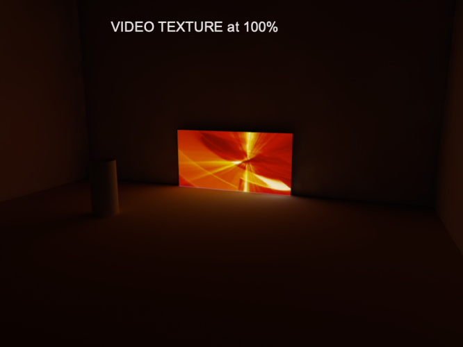
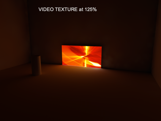
125% is generally my default. My opinion is that most LED displays will emit more light than that even when the NIT level is dialed back. I often help things out a bit by adding an “ambient” light or two to a render.
-
1
-
-
9 hours ago, mjm said:
Ty @scottmoore Did you need to edit the base image?
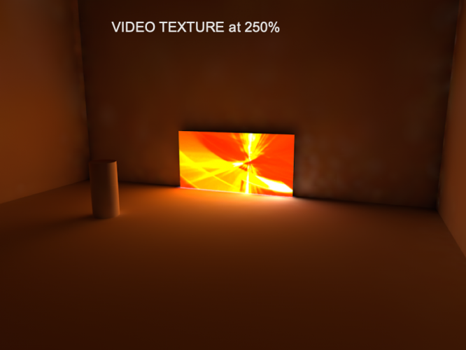
No. As you can see, at 250% the image gets quite blown out. I generally find that I can’t go much over 125%-135% before the image becomes unusable. Of course, that also depends on the image.
-
1
-
-
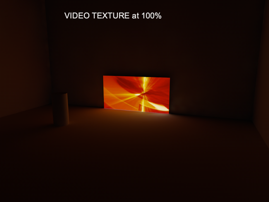
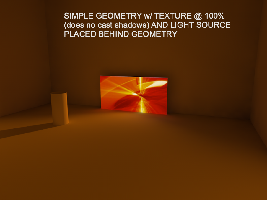
A few examples depicting light emitting displays. The room in which this display is placed is 100' x 100' x100' and just uses white as a finish. Another note is that the screen tool applies the texture to BOTH SIDES of the face so if you want to block the back side from being visible or emitting light you need to make the base structure the same size as the modules. Likewise, in the example where I included simple geometry to create a screen, you would also need a blackout piece of geometry in the back. In this case, it would also NOT cast shadows.

-
3
-
-
On 1/8/2021 at 9:27 AM, Pochflyboy said:
How do I make an LED screen actually emit light in renders?
It seems to not have any back luminance emitting from the screen in "REALISTIC SPOTLIGHT" renders. This seems to be true for television screens and projection screens as well.
Also note, if you want to actually see the glow you will need to a) enable indirect lighting, which incidentally is true of any glow texture that emits light, and b) you will need at least one other light source in the drawing so that you can turn the VWX ambient light off. For instance, if you just want an LED wall to illuminate your scene, you will need to turn off ambient light and place a light object with an intensity of 1% and possibly even give it a dark gray color. The light object will effectively be “off” but VWX won’t know that. If you have no legitimate light object in the scene, VWX will turn on the ambient light by default.
-
1
-
-
I tried it. Didn’t work. Since the glow texture emitting light is not actually a light source that VWX recognizes, it does not penetrate through a piece of geometry that includes a texture that does not cast or receive shadows. Kind of a drag as that would have been a useful tidbit. You can certainly put a light object behind that texture but getting the shape of the light source correct would be a nightmare.
-
1
-
-
On 1/8/2021 at 11:18 AM, Kevin Allen said:
The texture should have a Glow shader. It's typically at 100% but can be set higher. Too high and the image will blow out. Emit Light should be checked in both eh edit Shader dialog and in the Indirect Lighting dialog.
You won't get any beams of light, but you should get the effect of light.
Which brings up another question: how is that output actually calculated? I tend to find that I cannot get enough light out of a display to render realistically before the image blows out.
As I am writing this it occurs to me that perhaps I should let the image blow out quite a bit. What I will try is duplicating the texture with one completely blown out and the second at a normal intensity, however, set the second not to create shadows. Then I place the blown out image on my screen PIO, create a simple piece of geometry in front of the screen and map the second texture there. That should give you the best of both worlds. I’ll give it a shot when I have a minute.
-
Matt, thank you for that insight. That might then get us back to the RW camera dpi setting vs the sheet layer dpi setting vs the rendered output dpi setting conversation. 🙂 It still baffles me a bit but I just stick with the sheet layer dpi.
Regardless, being able to accurately render on the design layer should be a standard part of the design process. Anything else, including render bitmaps (terrible) is a massive distraction from the process itself.
-
Perhaps to clarify why I think this is important:
if I am developing a new texture (that may include reflectivity, bump shaders, transparencies, or luminosity, NONE of which can be seen in OpenGL) I want to look at that texture in use immediately so I can make changes as needed. Often it requires several passes to get a texture the way I want it. To do so, I center up the item on my monitor and use a keyboard shortcut to render. The rendering starts from the center out. Often times it only takes a few seconds to see what I need to see and then I just go back to wireframe and adjust as needed. Likewise, the same process is used for investigating lighting, gobo textures, shutter cuts and any number of items that require a quick reference so as not to have to waste time later. This should be easily accomplished directly on the design layer.
I have generally found that design layer renders (which I believe are 72dpi) look pretty great. Sheet layer viewports of similar quality typically require 150dpi or higher to look comparable and take longer because of it. I don’t really understand why that is.
For what it is worth, I used to do all my output rendering from screenshots of the design layer before I figured out sheet layers. There was never a problem until fairly recently.
-
This has been going on for quite some time. There are plenty of comments about this. Perhaps search “render cache”.
I will say that I’ve not seen it nearly as much in the past year or so. Actually, I am not sure when the last time I saw it might have been. I am on 2021.
-
1
-
-
On 4/25/2018 at 7:27 PM, Andy Broomell said:
So I just embarked on a project that has 2000 of a particular type of object. This object comes in 14 different sizes; each size is a different Symbol. Each of those sizes comes in any of 8 different colors. In the rendering we want some of every possible option... The permutations of doing this manually is a bit overwhelming.
If I could just have 14 different symbol definitions, and assign the 2000 instances to 8 different classes to control the color, it would save me hours of time.
As it stands I'll technically need 112 different symbols (though I'll probably fake it and leave some combinations out of the rendering).
Having a "BySymbol" option for attributes would be a HUGE step forward.
Ok so 2 1/2 years late and this would still be a workaround, but what if each of your 14 symbols became lighting devices and the texture that needed changing received its color by object and the particular geometry to which this texture was applied received its color by class and you made that class a “lens” class? Then all you have to do is assign a color to the “lighting device” and it would change the texture color of each individual item. Don’t forget to set your Spotlight preferences to allow fo this.
-
While this doesn’t really help you, I’ve always been a MBP user and have never run into this issue. I do a ton of rendering in VWX. So long as my laptops have been on a power adaptor, I’ve never even considered battery life. That seems really odd.
-
1
-
-
Works great as export PDF with layers. Just did a test file.

-
4
-
-
Ok, so first thing is I wasn’t aware you could export PDF with layers. Seems like this will work like a champ. Stand by...
-
Sean,
I am bringing this topic back up as I just bought a Glowforge Pro and am interested in your process. When exporting a PDF, should I assume that line/fill colors can be used as scoring, engraving and cutting?
Some experimentation today is in order I think.
-
On 11/5/2020 at 2:58 PM, P Retondo said:
Thanks, klinzey, I will check out those situations. Regardless of that, this is a user interface problem that VW needs to rectify. There should be one and one place only to set the visibility and shadow-casting properties of a light source for ALL rendering modes, and other toggles that affect this behavior should be removed. I had not noticed these changes up through vw2017, but since I started using vw2020 all of a sudden my former methods for lighting are not working.
I would tend to disagree with this. It is crucial to be able to have the potential to cast shadows or not per texture. If you place a light object inside a piece of geometry, the texture applied to that geometry needs to not cast shadows in order for your light to work.
Not casting shadows is often helpful when using process renders when you want to investigate how things look without waiting for shadows to render.
-
11 hours ago, Tom W. said:
I agree with @scottmoore the best way to scale a group of objects from the centre is to use the Modify > Scale Objects... > Symmetric By Distance command. And don't be like me + ignore for years the little dims buttons to the side
 : they allow you to quickly take dims direct from the drawing which speeds up the process considerably!
Or just use 'Symmetric' option + add a factor of 0.5 or 2 to half or double the size of the group or by whatever factor you want. Again, will scale from the centre by default.
I was a late adopter of that button as well, but certainly speeded up the process once I realized it was there!
The thing about a CAD program like VWX is that accuracy is really important. That is why there is less interactive than you might suspect. Sometimes that can be a downfall when you “just want to make that tree a little bigger”.
-
Not exactly what you are looking for but “scale by distance” might help you. I find it to be rather quick.
-
16 hours ago, bcd said:
For now - a Floating Multi Pane View of a low res Sheet Layer Viewport off to the side is probably your best bet.
Allowing you to work in OGL in the Design Layer unencumbered.
True, but it is far more time consuming than simply rendering on the design layer. I’ll give that a shot.


Export to Glowforge?
in Troubleshooting
Posted
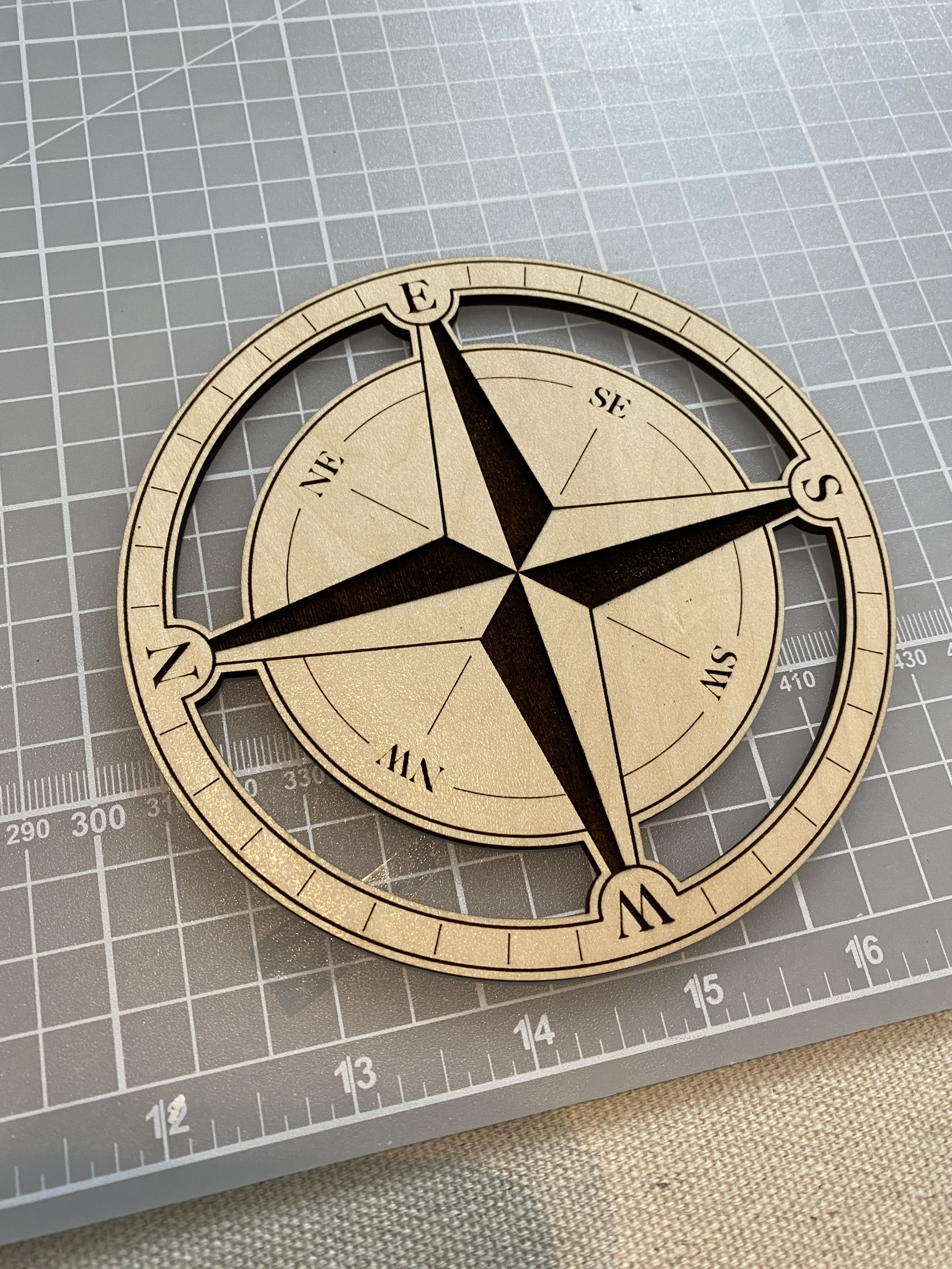
Great info as always Sean. I've not run into too many issues with this and have frankly found that just using colors as opposed to layers or classes has worked fairly well. Then it simply becomes an issue as to how best to organize the drawing in the first place. Attached is an image of a map I made of our downtown area as a project for my wife's side hustle. This thing is a bit addictive.