
MaltbyDesign
-
Posts
257 -
Joined
-
Last visited
Content Type
Profiles
Forums
Events
Articles
Marionette
Store
Everything posted by MaltbyDesign
-
Thanks @zoomer I think I got it to work with the "Delete Wall Peaks" and then selected the walls that I wanted to fit to the roof individually and that seemed to work.
-
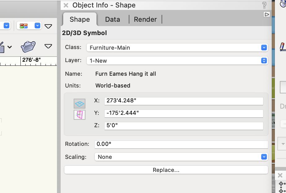
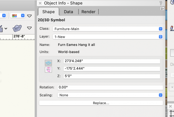
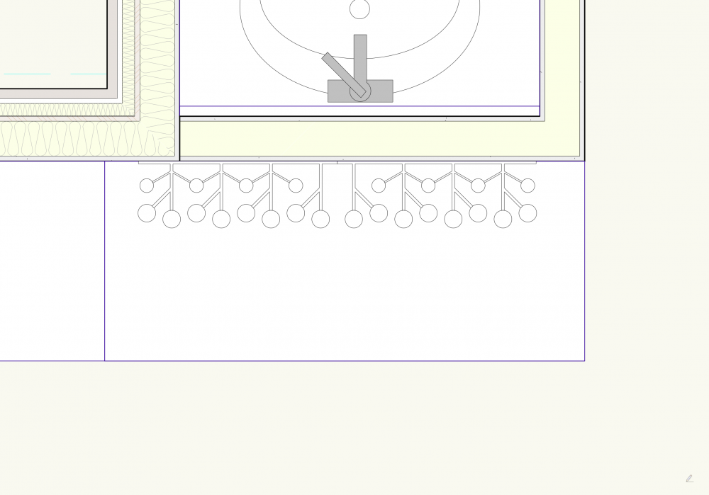
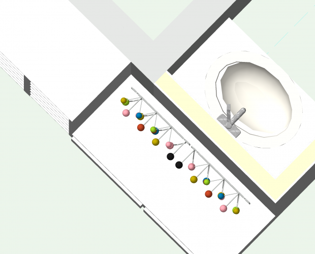
This is an issue I've notices with a few 2D/3D symbols in the past but never asked about. I just noticed this the other day with the "Furn Eames Hang it all" symbol; in 2D (plan) I place the symbol on a wall. Simple. But when I view in 3D in OpenGL, the symbol is now floating about 6" off the wall. The height is correct but it seems to have sifted its location on the X,Y axis. I noticed this a while back with some other 2D/3D Symbols (pillows, I think). Is there a fix for this? I've attached some images for reference.
-
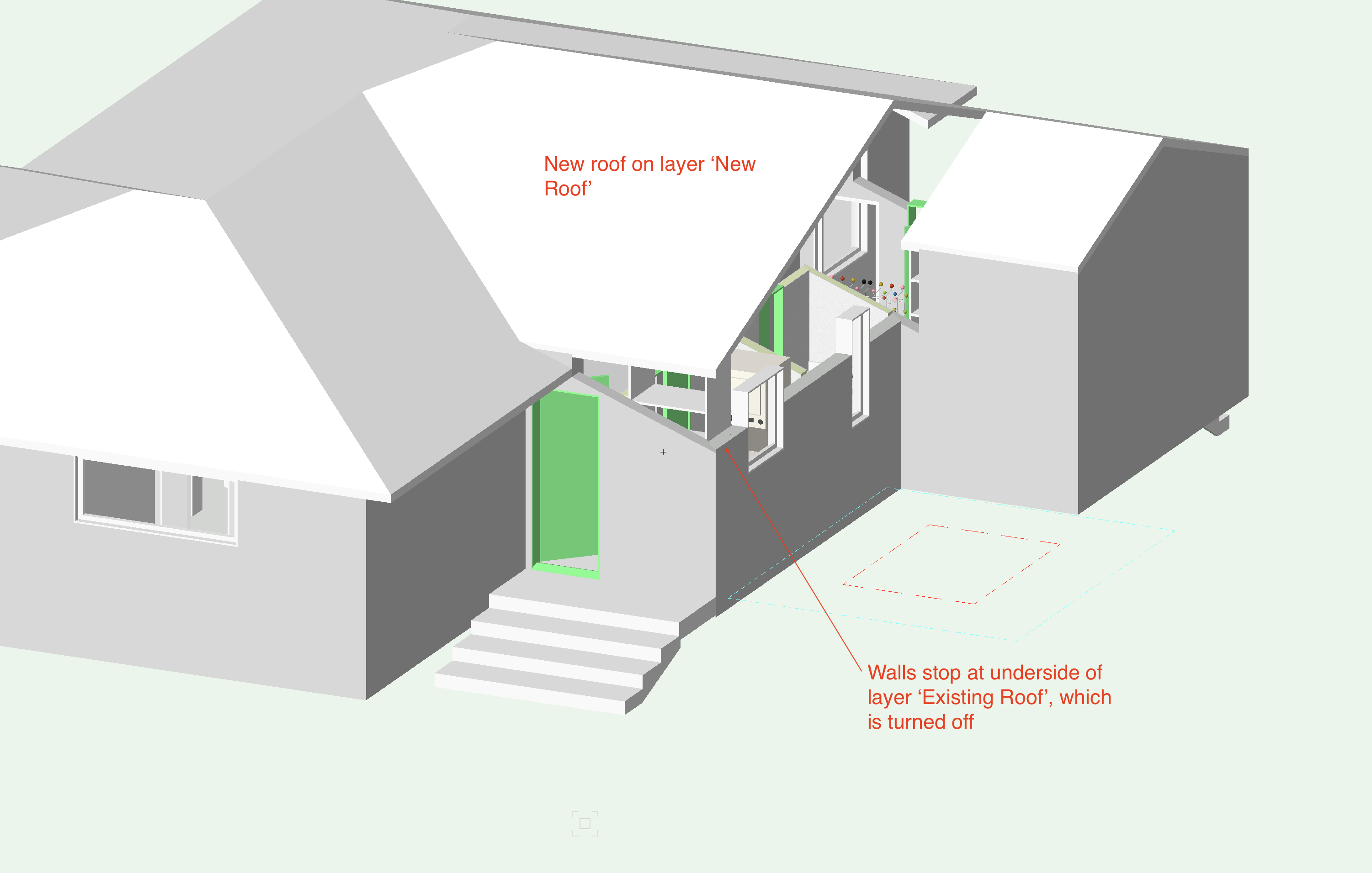
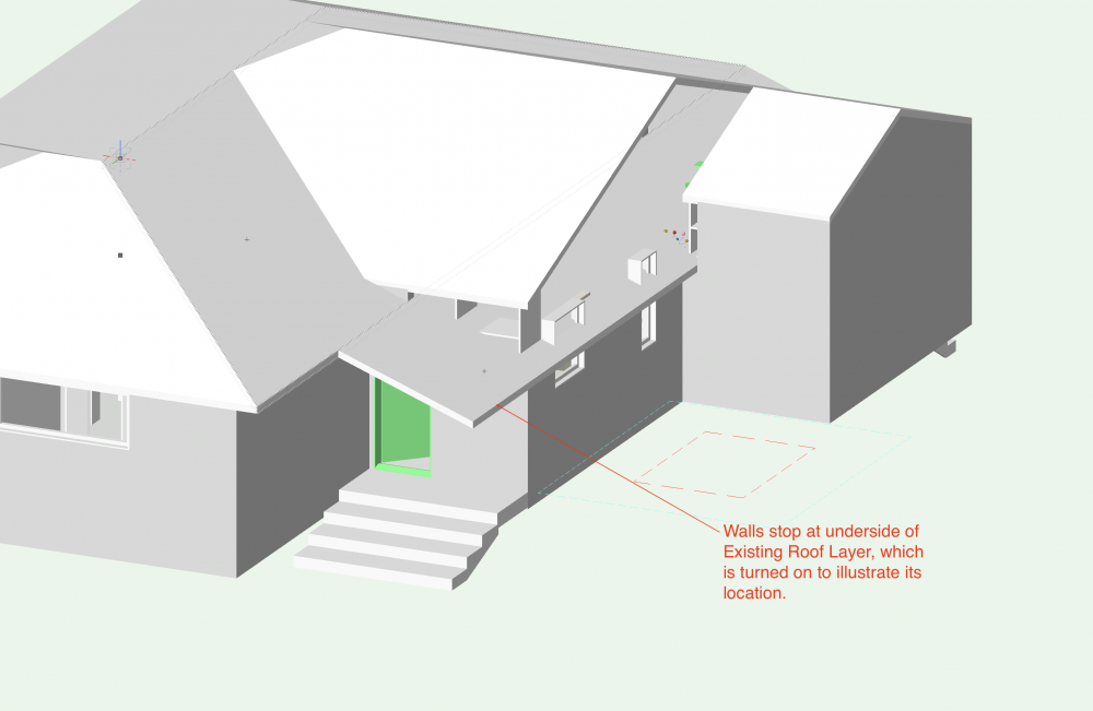
@zoomer The first image shows both the new and existing roof. The shed roof is part of the existing roof. So I created a layer for the existing roof and a layer for the new roof. When I used the "Fit Walls to Objects" command, I set the walls to extend to the layer 'New Roof' but it seems to be defaulting to the existing roof, even though that layer is turned off.
-
Hello All, I've run into a bit of a snag with a small renovation/addition project. I'm building a renovation model that show existing, demo and new layers. and edition with a shed roof is being removed and a new addition and new roof added. The new roof will marry to the existing roof of the main house in the same place where the demolished shed roof was located. Everything is fine until I try to fit walls to object. In the area where the demolished shed roof is located, this command seems to default to the underside of the demolished shed roof despite asking it to extend to the underside of the new roof layer. The existing roof layer is turned off. Why are the walls defaulting to the underside of the existing roof layer (layer off) and not the new layer (layer on)? I've added a couple of screen shots of the house rendered in OpenGL to show the situation.

-

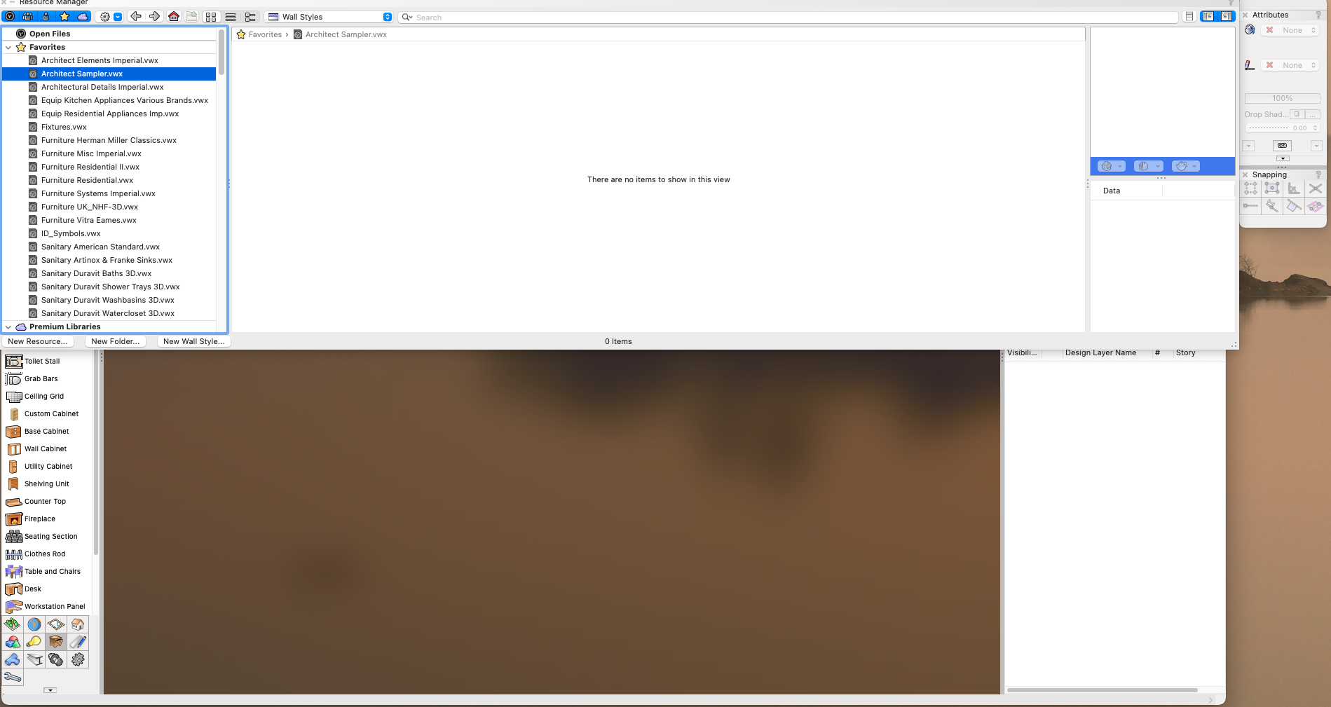
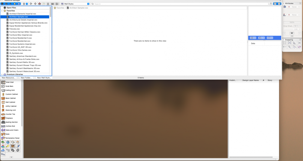
Resource Manager Libraries empty?
MaltbyDesign replied to MaltbyDesign's question in Troubleshooting
@Andy Broomell great idea! Also glad to know it’s not just me. -
Resource Manager Libraries empty?
MaltbyDesign replied to MaltbyDesign's question in Troubleshooting
@zoomer Argh! I wasn't even looking for the simple solution and thought there was a bigger problem! Thank you for seeing what I couldn't! -
I'm using VW 2021 SP2.1 and all of the Libraries in the Resource Manager show no items when clicked on. Scree Grab attached. It works fine in VW 2020 but for some reason there seems to be a problem in VW 2021. I checked the Session tab in preferences to ensure "Enable VW Libraries" was checked. Any suggestions?
-
How do I model a Saltbox Roof (Asymmetric gable)?
MaltbyDesign replied to MaltbyDesign's topic in Architecture
@taoist Because I know it backwards and inside out. I've been using it since release 10. It's required software for most of my work. I've been using VW for a few jobs here and there but haven't reached the skill level where it's not a struggle. I'm hoping to move to it completely, eventually but this project won't be it. -
How do I model a Saltbox Roof (Asymmetric gable)?
MaltbyDesign replied to MaltbyDesign's topic in Architecture
Thanks again for the tips, all. I think I've got the roof figured out but got bogged down again with Storeys and trying to model an existing home and figuring out existing and new construction. Back to 2D drawing in AutoCAD for this project. I think I'll reserve 3D for new builds only, for the time being. -
How do I model a Saltbox Roof (Asymmetric gable)?
MaltbyDesign replied to MaltbyDesign's topic in Architecture
Thanks very much for the info. @jeff prince I'm not sure I follow your process. I'm going to have to spend some time studying your drawing to see if I can't figure it out. I appreciate the time you spent on this. -
So is using Storeys for house design just adding unnecessary complexity to drawing?
-
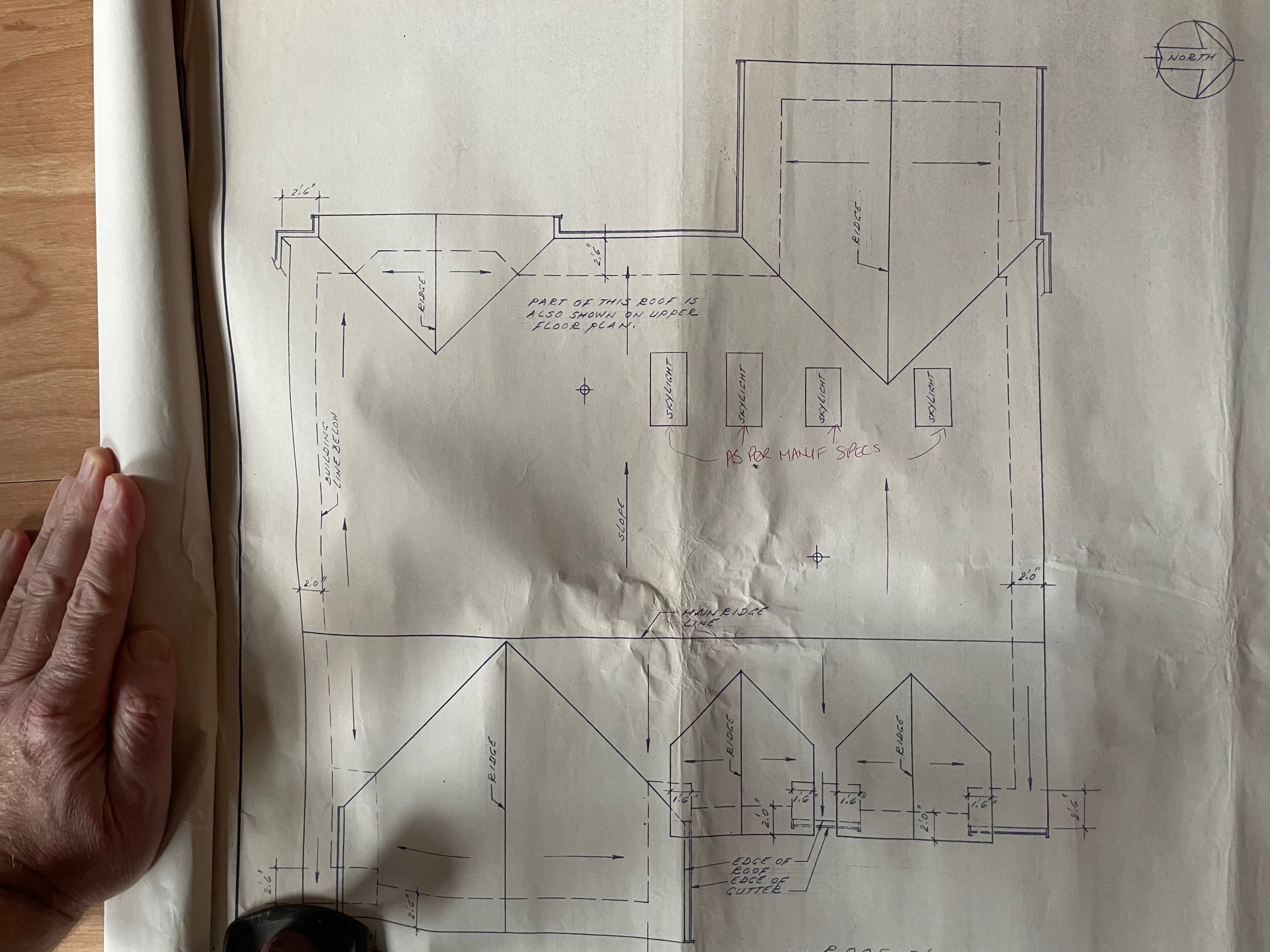
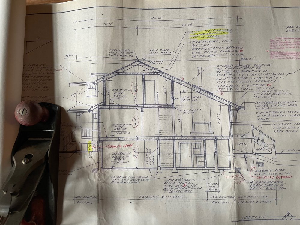
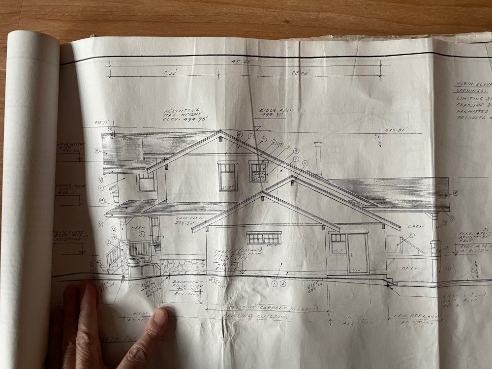
Hi folks, I'm preparing a model of an existing house which will have an addition added to and it has a saltbox style roof (asymmetric gable). I've attached some images of a building section, roof plan and elevation for reference. The second floor steps back and is about half the width of the main floor, resulting in a roof that spans from the top of the wall at the second floor to the top of the wall at the first floor, forming a double height volume resulting in the asymmetric gable. What is the best way to model this roof that allows me to add the gables and skylights easily? I don't need a lot of detail in the roof object, as the existing house will be treated as a simple white object in 3-D.

-
@Wes Gardner thanks for that. I'm getting fairly familiar with using stories with layers, so think I'll stick with that approach.
-
@taoist Do you find one of the three methods works best?
-
Any Advice for Setting up Walls When 3D Modelling Renovations
MaltbyDesign replied to MaltbyDesign's topic in Architecture
@Boh That's what I was assuming. That the modifications would only happen on the second model, showing new construction. -
Any Advice for Setting up Walls When 3D Modelling Renovations
MaltbyDesign replied to MaltbyDesign's topic in Architecture
@Boh Thanks again. -
Any Advice for Setting up Walls When 3D Modelling Renovations
MaltbyDesign replied to MaltbyDesign's topic in Architecture
Sorry for the late reply @Boh . Thanks very much for the detailed response. I think I understand your process for working in plan but with the existing model having objects demolished and, effectively, deleted from the model does one need to have two models? One model showing the entire existing building and then one model showing all of the modifications? It seems to me that it would be really difficult to show both demolition and new construction in a single model. -
Any Advice for Setting up Walls When 3D Modelling Renovations
MaltbyDesign replied to MaltbyDesign's topic in Architecture
Thanks for the input, zoomed. -
I do a lot of home renovations but typically do those drawings in AutoCad because it's quick and easy. However, I then often end up having to model in SketchUp to help homeowners visualize spaces. I'd like to be able to handle the entire workflow in Vectorworks, which I typically use for new builds. I'm having trouble figuring out how to model in 3D in a way that I can show the walls of the existing home, the walls to be demolished and the new construction. I tend to define a set of classes for the existing house with the prefix EX while new construction gets prefixed with CD (construction development/document). This works well for 2D drawing but I'm having trouble trying trying to figure out how to set up a drawing for 3D modelling. Does anyone have suggestions for a seamless way to integrate classes in a 3D model that clearly shows existing, demolition and new construction? In AutoCad 2D draughting it's just a matter of creating a plan where layers (classes) are toggled on and off to show the desired information. I'm having trouble trying to figure out how to achieve this in Vectorworks 3D drawing. Any recommendations or examples of workflow would be greatly appreciated. Thank you!
-
Showing atmospheric depth to exterior renderings
MaltbyDesign replied to MaltbyDesign's topic in Rendering
You're right. I forgot that opacity doesn't work for extrusions. If only I could draw a rectangle along the z axis and then give it a radius, so that it is effectively like a curved (along the x-y axis) curtain or arched screen. Then I could use opacity. But I tried my extrusion idea and gave it a clear glass texture and removed reflectivity. That seems to work okay (need to fiddle with the texture settings to optimize). I created the extrusion from an oval so that it surrounds the building and would work for any view. -
Showing atmospheric depth to exterior renderings
MaltbyDesign replied to MaltbyDesign's topic in Rendering
Thank you for these suggestions. I'll give them a try. Your first point gave me an idea; I wonder if, in plan, I could create a series of 'curtains' (vertical extrusions) with varying opacities and set them at different distances apart. I'm think of these curtains as concentric circles so that the view chosen doesn't matter. Have them on a class that can be turned on and off easily. Just thinking 'out loud'. -
I'd love to be able to show depth on my exterior perspectives by trying to add some atmospheric depth to the background (the atmospheric filtering or layering that we see as objects get further away from us). I thought I might be able to control the opacity of trees and other background images to achieve this but that doesn't seem to work. Then I thought perhaps there might be a way to do this by adding exterior lights and using lit fog but that doesn't seem to achieve anything either. Can anyone point me in the right direction? Is there a guide to exterior rendering that illustrates how to get reasonably realistic depth of view? Aside from shadows being cast, everything looks so flat as though the background trees and building are on the same plane.
-
@Alan Woodwell Thanks so much for this bit of information. Very useful! This will help me get a solid 'skirt' with a textured ground surface.
-
@markdd That did the trick! Thanks very much for the suggestion, I appreciate it.
-
Hello, I've made a coloured glass backsplash that should be completely blue in the attached photo. However in render works it shows swaths of white that shouldn't be there. Any ideas what might be causing this? I thought it was the lights I installed but I've turned them off and still get the white. Thanks for any suggestions.