
MaltbyDesign
-
Posts
257 -
Joined
-
Last visited
Content Type
Profiles
Forums
Events
Articles
Marionette
Store
Everything posted by MaltbyDesign
-
 @Tom W. If the top of your finished floor is 0.0, you then would have to offset the bottoms of your walls to sit on the subfloor/slab. I guess it's a trade off. I just had a thought; If you set 0,0 to the top of subfloor/slab and want skirting boards, fixtures and fittings to sit on top of the finished floor could you set up a fixture and fitting layer that is offset from zero by the thickness of the flooring? So when you insert furniture, millwork, etc. it is at the right elevation to allow for the finished floor thickness.
 -
@zoomer where I live, the finished floor is the last thing to go into a building except for baseboards, trim and cabinetry in some cases so, interior walls and door frames sit on the subfloor/slab.
-
@line-weight I tend to think of things in terms of how they are built. Whether that's the right thing to do in 3D modelling I don't know yet.
-
@zoomer if walls, etc. are above the finished floor elevation, do you offset the bottom of walls to sit on top of the subfloor/slab below?
-
@Tom W. actually, I think I started including finish floors in my overall floor assembly so that top of finish floor was at 0.0 but quickly changed that and went with what Wes suggested. personally, I would have the bottom of the floor finish sitting on 0.0 and handle the difference in floor finish with floor transition strips just as handled in real life (carpet to wood floor transition strips for example which can be wood or extruded aluminum)
-
@zoomer Actually, I think I did that with my last model as well. Set the finish floor top at 0.0. If you set top of structural slab at 0.0 then you have to offset door sill, millwork and furniture according to finish floor thickness.
-
@Tom W. I add floor finishes to the top of the structural slab/framing which has an elevation of 0. You could handle the difference in floor material thickness the same as you would in real life, with transition strips.
-
@Tom W. Is the brick a part of the plinth wall assembly or is it a separate element? I've never heard of a 'wall hole component symbol'. Can you explain this? Thanks!
-
@Tom W. I meant to suggest that as well and having the light source turned off seems the most likely problem. @Dcrb some of the render styles have the ability to turn shadows on or off in their preferences.
-
@Tom W. Is your outer weatherboard (siding) drawings as a separate object from the wall, or is it part of the wall style? Is the flashing a linear extrusion?
-
Could it be your shadow settings in the render style?
-
@bwfowler I find that with smart points on I can hover the cursor to one side of the wall and then to the opposite and then it identifies the 'imaginary' midpoint to click on. In 30+ years I've never been in an office that dimensioned to the centreline of walls. Always to the face of stud for interior walls as it's easier for framers to snap a line.
-
Referenced Viewport on a Site Plan Question.
MaltbyDesign replied to MaltbyDesign's topic in Architecture
@jeff prince I think I used the same process as you and I've got everything working as it should. Thank you. -
Referenced Viewport on a Site Plan Question.
MaltbyDesign replied to MaltbyDesign's topic in Architecture
@Jesse Cogswell Thank you! I got rid of the crop object and everything seems to be working properly. The clip cube behaves as it should. -
The midpoint should be snapped to automatically when you move your curser to the middle of the wall. You may not have your Snapping Tools set up to use 'smart points'.
-
I created a site plan model (digital terrain model) and inserted my building model as a Referenced Viewport. My first problem was the building model disappearing and I discovered that I needed to increase the crop area of the viewport so as not to crop the model itself, depending on the view. Fair enough. However if I switch to a front, right, left or back view, the building model disappears and the crop outline is far removed from the site plan (back down to z=0, despite adjusting the building models z-value to bring it up to the same elevations at the site topography (which was created using real elevations so the site plan is 690' above zero. What's causing this and how do I fix it? The next hurdle is that I now see that if I use the clip cube command through the site plane, the site model gets clipped while the building model doesn't. A section viewport does create a section of both the site and the building model reference, so that's a plus. I'm assuming I'll be able to modify the site model with the building model as a referenced viewport in order to remove the earth from the basement, so to speak. I tried this method as I saw it mentioned in various posts about adding buildings to site models. But is it the best way for small, simple projects? Am I better off drawing the building and the site model in the same drawing file and adjusting my main floor elevation to the correct geodetic height?
-
@line-weight Thanks for the additional detail. I'm working on a small renovation/addition right now and decided to bite the bullet and do the whole project in 3D in Vectorworks. I could be finished it if I were drawing in 2D with AutoCAD, but am determined to use this as a learning experience and hopefully become confident enough to take the jump to 3D for all my future projects. I don't mind 'donating' some of my time to learn the process on a real project. Part of the reason for this post was to explore what others are doing and if they've found that 'sweet spot' in efficiency. It sounds like we're all forging paths that work best for us. I tried Storeys on this project, just to try and get my head around it. I'm not sure it makes total sense for small residential projects but I think it could be useful for larger projects. The jury is still out on it, though. Because i'm working on an addition/renovation to an existing home, I'm finding classes to be quite useful. Particularly in controlling visibilities. They are much the same as layers in AutoCAD in that regard. I do like the fact that I can have a Zoom meeting with the client and rather than show just flat elevations and plans, I can show them the building in 3D. I think it helps them to understand it better than just plans and elevations do. So this saves me having to do a quick sketchup model when clients are having trouble visualizing things in 2D.
-
@line-weight Interesting. When I draw in 2D (AutoCAD) I tend to draw building sections with quite a lot of detail where I need it. Window and door heads, sills, wall/roof connections, parapets, etc. Then it's just a matter of drawing them only once in the context of the overall building assembly and then referencing to a different sheet at a larger scale and adding text. If I make changes to the main section, those are them reflected on the details as well. After 30+ years of drawing in 2D, I've developed a nice mix of brevity and information in my drawings that, I think work well. Now with 3D, I'd like to try and find that sweet spot where a drawing, or model, is developed to show enough information to be usable for contract documents. If you are building a model stick by stick, do you use storeys? Or just stick to Design Layers? Also, I assume that a lot of your drawing information is put on a large number of classes that act as containers for the various parts of the assembly (Structural wall framing, floor framing, wall sheathing, finishes, etc.).
-
@Boh Thanks for the tip!
-
@Boh I can see that as being a benefit. Right now I'm working on an addition to an existing house and am trying to draw things in a way where more detail is shown on the addition so that it graphically stands out from the existing while still showing the existing accurately. I think, like you, I see the modelling as a tool to quickly and accurately generate elevations, overall sections and plans for both presentation and contract documents. I suspect I can be more efficient with my time by generating details in 2D.
-
@Boh thanks for the links. It sounds like you do the same as what I've been doing, according to your post in the first thread:
-
Hi all, this is a question for other architects and residential designers who model in 3D. How much detail do you put into a 3D model and how does that transition to your contract documents? I suppose one could spend quite a lot of time building a model 'stick by stick', as it were, so that when you create section and detail viewports, your viewports are showing an accurate representation of what's to be built. However if one is using wall, slab and roof styles, the detail and section viewports will show section outlines without much detailed information. In the past this is what I've done and then on my sheets, I go in and add to the sections and details in 'Edit Viewport - Annotation', using the detail or section viewport as a base to start from. So, I'll add dimensional lumber, window/door heads, flashings, etc. I suppose if one were modelling in true BIM, everything would be accurate and there'd be no need to add anything to details and sections other than notes. For residential projects, I'm not sure this would be time well spent as it seems to me that the time spent modelling to this degree would be a money losing proposition. That may be an assumption based on my own level of proficiency with 3D modelling. If you model in 3D, how far do you take it? Do you model absolutely everything - put lots of work in to the front end to save time (hopefully) in contract document production? Or do you model for the 3D form to convey the necessary information for plans, elevations and basic overall building sections and then build up larger scale, detail sections similar to how they're done in a 2D workflow? I'd love to hear from those in the industry for what works for you and if you've found a 'sweet spot' in your work flow. Transitioning from a 2D workflow (AutoCAD) to a 3D workflow presents all sorts of challenges but I'm hoping to be able to become efficient enough with Vectorworks to be able to say goodbye to my annual AutoCAD subscription for good. Thanks in advance.
-
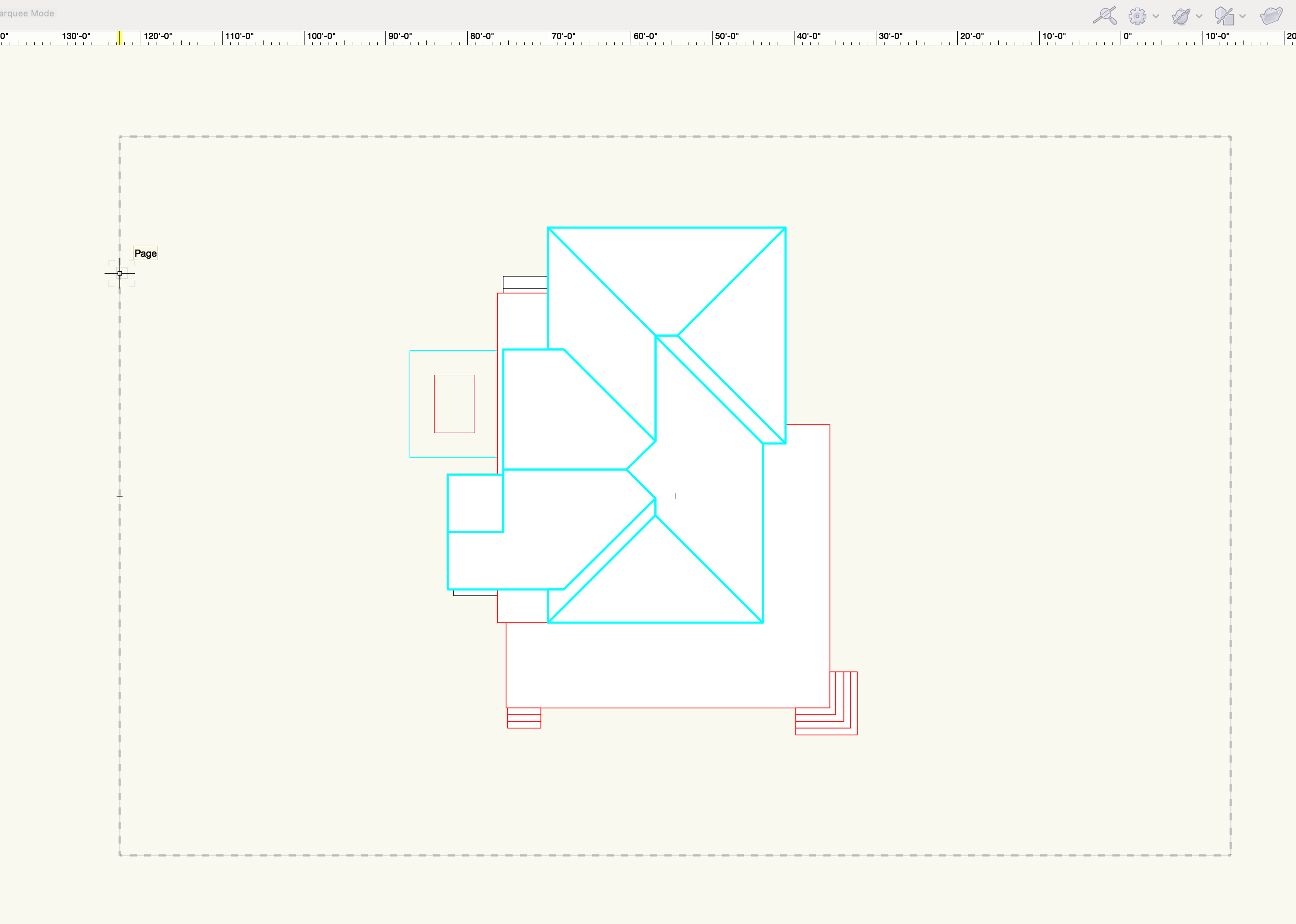
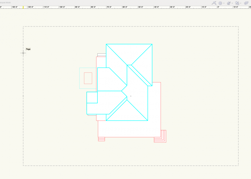
Page Boundary and model not centred at 0,0
MaltbyDesign replied to MaltbyDesign's topic in Architecture
@Tom W. Thanks Tom, that solved the problem quickly and easily. -
Weird thing that I just noticed on my drawing. Typically a page boundary is centred on 0,0 but mine is not aligned at all. Also, my model is way above 0 on the z-axis, despite my layers set to a base of 0. Any ideas what caused this and how I can reset it? Thanks very much.
-
@Pat Stanford Thanks very much for that. That did the trick.