

- Popular Post


P Retondo
-
Posts
1,914 -
Joined
-
Last visited
Content Type
Profiles
Forums
Events
Articles
Marionette
Store
Posts posted by P Retondo
-
-
- Popular Post
Surveyors produce typical boundary descriptions according to their methods - not according to the logic of the Vectorworks tool.
Issue #1: bearing direction. Please include a button to quickly reverse the direction when the property line tool goes the wrong way
Issue #2: redraw - often, VW fails to draw a line, although it later becomes apparent that it stored the info the first time, and we get an incorrect boundary
Issue #3: data entry - once you click "Add" the segment should actually draw (see above) and the fields should automatically clear, signalling to the user what is next required.
Issue #4: editing the PL - the segment we are editing should be highlighted, instead of making us guess which one it is
Issue #5: panning - the shift key to allow panning while in the tool dialog box does not work, so if your line happens to go off screen you can't see what is going on
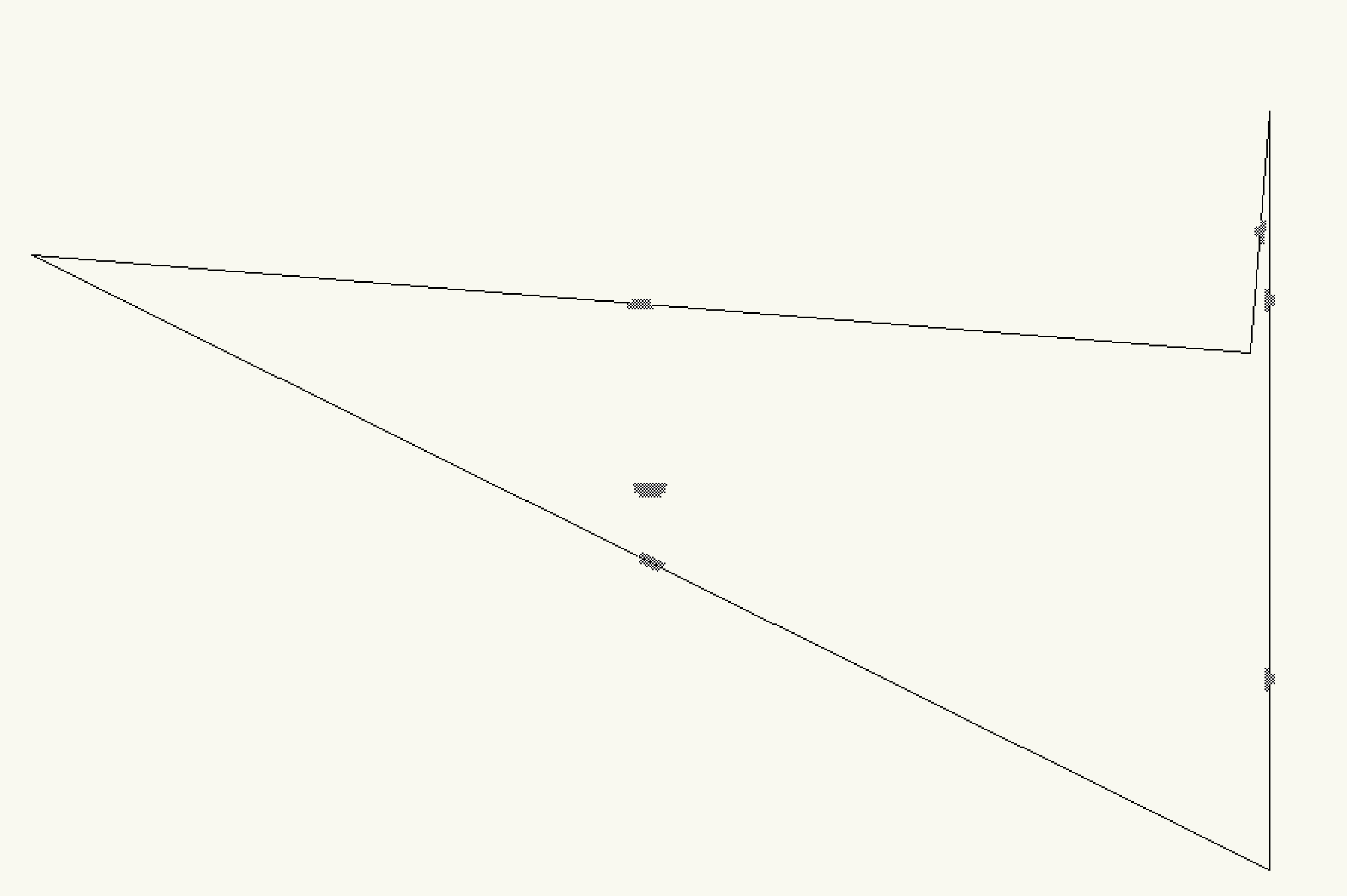
Issue #6: arcs - this, as far as I can tell, is almost beyond redemption. Here's the result I get after entering 3 segments, the last one an arc, starting from the left and running counterclockwise:
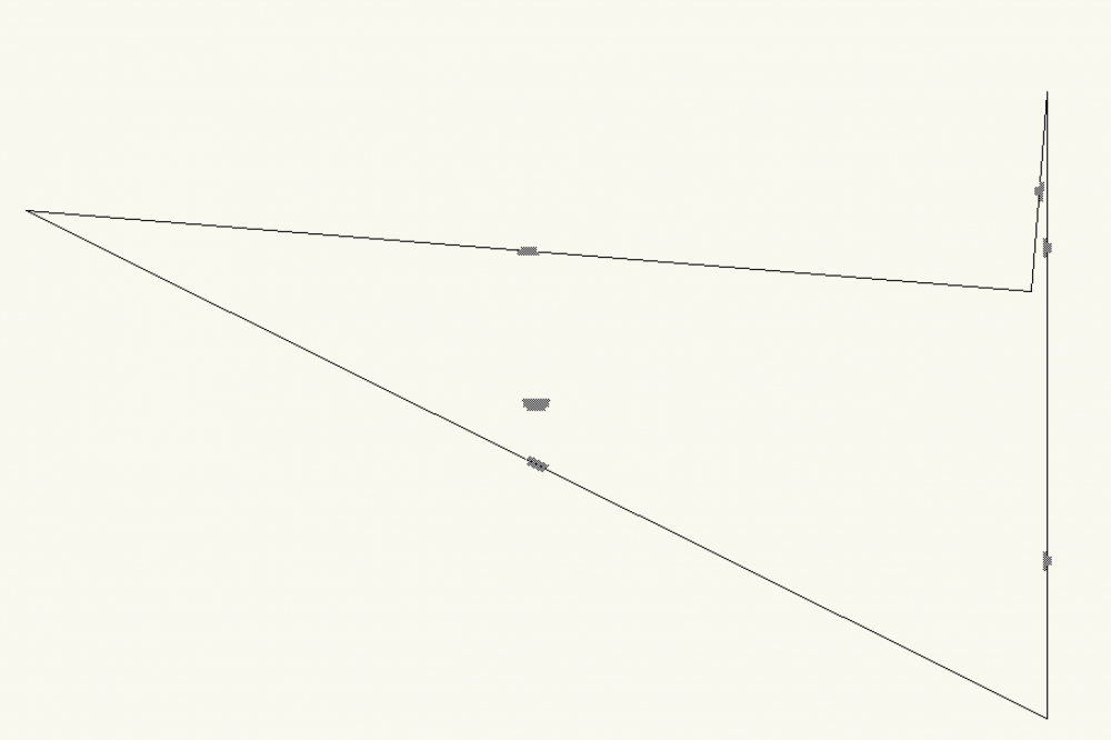
Here is what the property line looks like:
Clearly, the program selected the incorrect bearing to start the arc, even though I entered the exact same bearing that was used to generate segment 2. Now, perhaps I can go back and change that bearing, and lord knows what will result. The tool is just unbearably difficult and unpredictable! By the way, you have to know to clear the previous bearing information BEFORE clicking on the arc button. And FYI, trying to correct a direction mistake by going back fails almost 100% of the time, and we have to start over.
How about some real world testing to see if things work before calling it done! And we have been living with this tool for year after year with no improvements despite the many thousands of dollars sent to NNA. Think about optimizing the workflow, and making it easy to just enter a surveyor's information and end up with a property line. Should take no more than three minutes! Instead, I am fussing with this thing for hours.
-
 6
6
-
This is an old thread, I was looking for some guidance. But I have to say I completely disagree with everyone who thinks the property line tool is acceptable! The direction of next segment problem has been there since the beginning - a simple box to reverse is what is needed, and no one has apparently ever thought to upgrade the tool. Arcs are next to impossible. Enter the data, and you get a mishmash of multiple incorrect segments.
The idea of the property line tool is to generate a geometrically correct polygon. I've used this tool for years, and eventually after multiple trials and errors usually get something reasonably correct - but it shouldn't be so difficult. Now I am faced with a boundary that has two arced lines, and it's just impossible.
-
1
-
-
-
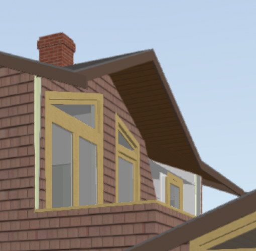
Modifying a window transom results in this nonsense with the wall:
-
Just crashed vw2020 (SP3!) again - froze after I clicked on a window in a 3d view. Tell you what, Nemetschek - I've been purchasing upgrades for 3 seats of VW Designer for years, waiting for you to make meaningful improvements. I'm tired of waiting and paying. Last year I cut back the number of seats, and this year it will be zero.
-
1
-
-
Thanks Ray, you have been incredibly helpful!
I just wonder if wrapping the SetPref function call in a procedure might be what earlier versions of VW require? (I guess I'm too lazy to check it out.)
-
Ray, just for reference, here's the script for a toggle command I've been using for quite a while. I can't remember the name of the person who posted it, it works in the form of a .vsm as a plug-in:
Procedure group;
begin
SetPref(14,not GetPref(14));
end;
run(group);
This script toggles "view other objects in group."
-
1
-
-
The original two line script worked perfectly in VW2020.
-
1
-
-
Thanks, Ray! 95 it is. I used Plugin Manager to create a plug in, and added the command to my workspace. 10 seconds x 1000 saved!
-
View 2d objects. I need to turn those on and off all the time when working in 3d.
-
Anyone have any quick guidance about how to change the 2d objects view preference in Unified View Options via a VS routine that can be invoked with a keyboard command? I wish there were a macro utility that could capture VW commands and automatically transform them into VS language the way Excel can with Visual Basic.
-
You can create a worksheet function. Assign a class to the lines you want to total, and create a worksheet cell with the following definition:
=LENGTH((C='[classname]'))
-
1
-
-
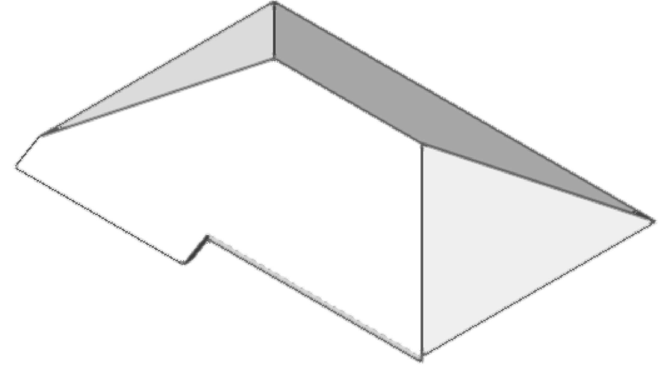
Starting with this roof:
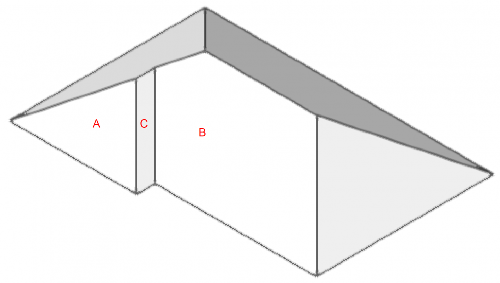
Ungroup, draw a polygon in plan that encompases A and C up to the hip of B. Get rid of A and C and edit B to incorporate that polygon. Then you end up with this:
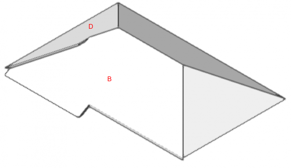
Faces B and D do not join at a hip. To fix this, join D to B using the same "Join" tool used to join two lines
Click D, click B, and get this:

-
Boh has the geometry basically correct. To fix this:
If your roof planes are not already separate objects, ungroup the roof object so that it is a set of roof planes. Then make a polygon that outlines the edges of your roof A, bearing in mind that it will extend beyond the eave of roof B as Boh illustrates. Then double-click on B, paste-in-place your polygon and add the two. Then, after exiting the roof plane edit space, join all your roof planes using the "Join" command.
The roof tool isn't designed to automatically generate a roof of this shape. If you start with a polygon, it will assume that you want all your fascias to be at the same height, and will add a valley and extra plane at the intersection of A and B. You have to go through the plane editing process every time you want to create a roof like this. I always start with a simple rectangle, get a hip roof, ungroup, and edit the planes. If you do it that way, you won't usually have to join planes, they will already be aligned correctly.
-
2
-
-
Top/plan viewports.
-
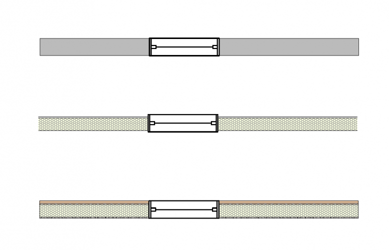
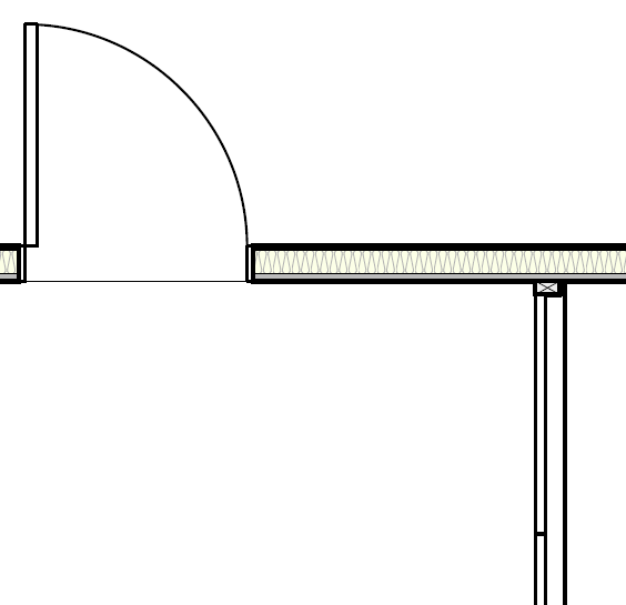
Wes, I actually construct my wall components in the way you do. I did a little experiment, and found that ONLY if you disable all of the component classes do you get an acceptable result. The image below shows (top): all component classes disabled, and I added a gray fill to your wall class; (middle): just siding and interior finish component classes disabled; and (bottom): no classes disabled. Although I think your suggestion is workable in most cases, I often apply the component classes to other objects in order to quickly assign the class attributes, and those objects will disappear if I follow your method. And besides, I still argue that the previous "show components" as a viewport option was easier and worked just fine the way it was.
-
I just jumped from 2017 to 2020. I haven't experienced the problem you have observed, but I seldom use hidden line rendering and have spent only an hour or two using v2019.
The best way to deal with top/plan view with this kind of object is just as you say, to create a hybrid 2d/3d symbol. A quick way to do that is to convert a copy of your 3d object, either directly to polygons or by composing a convert-copy-to-lines, and applying a fill.
-
1
-
-
My guess is that it's a bug or software limitation. If I were you, I'd do that unrendered portion as a separate rail and call it a day!
-
I've been using VW since 1994 MiniCAD. The original genius behind Vectorworks was Richard Diehl, who had this great idea of hybrid objects that showed elements in traditional plan view, but also intrinsically contained all the information to be displayed in a 3D view. As far as I know, he was the originator of that idea. When Richard sold the company, and even before that, he handed over design to engineers who, in my humble opinion, have not respected the pure genius of his original idea and have cluttered the software with their own less focused ideas. It is what it is, you won't ever "rip the lid off it."
-
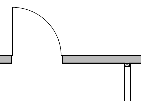
Wes, I used to uncheck "show components" in Viewport advanced preferences. I don't want to eliminate all the components or turn off classes, I just don't want to see components at 1/4". So that is a big change, and the "low, medium, high" detail settings are not at all the same. BTW, if I turn off component classes, things like gyp bd and sheathing just disappear, and all we see is the wall framing component. Sorry, but to me this is just one more example of VW sloppy engineering and lack of consideration for the professionals to whom their software is supposed to deliver for my yearly payments!
For example, viewport at "medium":

Same viewport at "low", missing door double line, jambs, and French doors in closed position:

Unacceptable!
-
Thanks, Mark - I double checked, and my Unified View settings include displaying screen and plane objects. Tried "active layer only" both ways, no difference.
Pat, the more I think about it, the behavior of screen 2d objects in 3d edit space is probably a bug. Try it.
-
Pat, thanks for chiming in. Following your suggestion, if I change my 2d preferences to "Working Plane Only," I can create a 2d object in the 3d edit space that persists as a "Symbol Definition" type (just the fact that this additional 2d object type exists is a red flag! Kluge!). If I use my standard "Screen Plane Only" preference, the object immediately disappears and is visible as part of the 2d symbol. If this difference in the result depends on 2d object preferences, I'd call it a programming oversight. If a Layer Plane object can be automatically converted to "Symbol Definition" type, so could a Screen Plane object.
I can't get an extrude to persist in 2d edit space - that's where I can't replicate what you are getting. It immediately disappears, and shows up in the 3d symbol. It actually disappears even before I complete the extrude operation. I don't understand why the "old way" had to be changed - if it ain't broke, don't fix it!
-
As I use 2020, more disappointments. Editing 3d portions of hybrid symbols is impossible, you have to create the object outside the symbol edit space, then paste it in. Can't turn off wall components in Sheet viewports without losing important door and wall graphics. Based on these alone, I wish I had stayed with 2017. I just have to wonder whether the engineers consult with actual architects when they make these changes, changes that in my opinion have no plus side. Hoping to find the silver lining promised by one of my trusted VW compatriots!
-
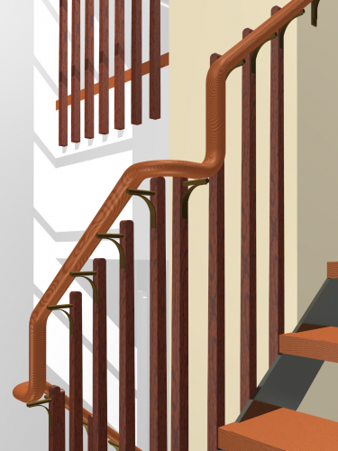
It's not the answer you want to hear, but I create a NURBS curve for the entire handrail and extrude-along-path. The system I use is to draw lines at the appropriate height in each elevation, convert to NURBS, draw arcs from above and convert to NURBS, reposition things so endpoints align (you can also join), then compose into a single NURBS. After extruding, edit the profile and reposition it - in your case, make sure the center of the circle is at 0,0. Example of a railing created by this method:


Can we fix the property line tool?
in Wishlist - Feature and Content Requests
Posted · Edited by P Retondo
@Pat Stanford
Pat, I always appreciate your point of view and your selfless dedication to solving problems for those in the community who are having trouble with the software. You are truly an inspiration. Let me help you understand where I am coming from. I studied software engineering at UC Berkeley Mechanical Engineering, and we were relentlessly taught to look beyond the "cubicle" and to work to understand all the unanticipated ways in which code can go wrong, and either not work or not meet the need. Over in the Computer Science building next door, maybe the focus was less application-oriented! (Friendly dig, there.) We were taught to challenge the code, to do very time-consuming step-by-step debugging, and to prove that it worked in the real world of mechanical devices. The big bad story was how early radiation therapy software killed some patients because of an unanticipated lag between software output and sensor input.
So when I try to use a tool like the property line tool, I am acutely aware that it is an example of code that was just quickly tossed off (maybe to check a box, as you say) - and besides being a pain in the rear to use, it has a real world impact on my productivity. You are absolutely right that it is not my job, or the job of any user, to try to fix this tool, not just because I pay to have NNA fix things like this, but because I just don't have the time. Got to make a living. So I end up being a complainer, but I hope I am an educated complainer in at least some fashion.
Your post gets to the core of the problem. You mention engineers, users and marketers (don't get me started on the Haas School of Business and MBAs). What seems to be lacking is that essential management level that would address user satisfaction and the success of the software in its application environment. VW could shine, and it just makes me beyond sad that it doesn't happen.