Cookie_NZ
-
Posts
81 -
Joined
-
Last visited
Content Type
Profiles
Forums
Events
Articles
Marionette
Store
Everything posted by Cookie_NZ
-

Data Manager - Adding additional lighting device parameters
Cookie_NZ replied to Cookie_NZ's topic in Entertainment
Hi Mark, Brilliantly simple. I hadn't spotted you can assign additional colour fields in Lightwright. Thanks for that. Cheers, Cookie -
Data Manager - Adding additional lighting device parameters
Cookie_NZ replied to Cookie_NZ's topic in Entertainment
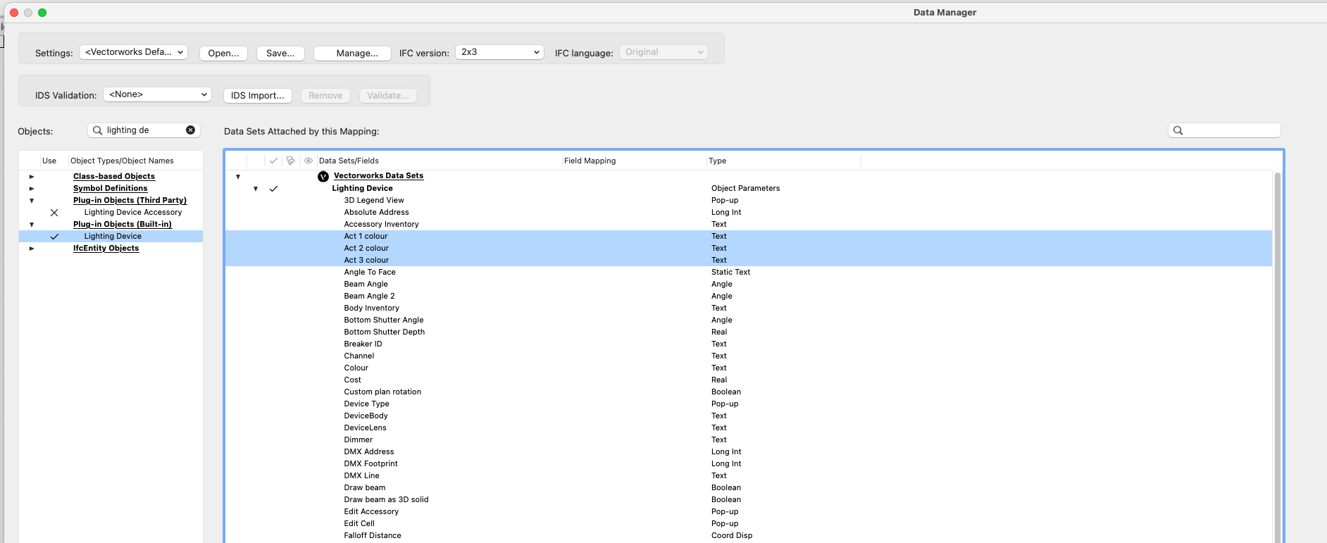
Hi Scott, On further investigation, it seems the issue is specific to the file I was working on. I made a test file to share on the forum, and the new fields are available in the Data Manager in the test file: I've messaged you a link to the active file with the issue. Cheers, Cookie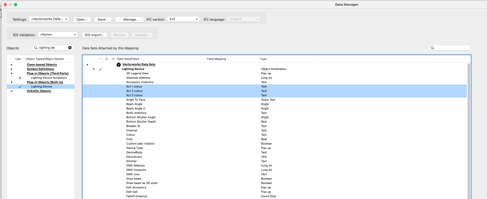
-
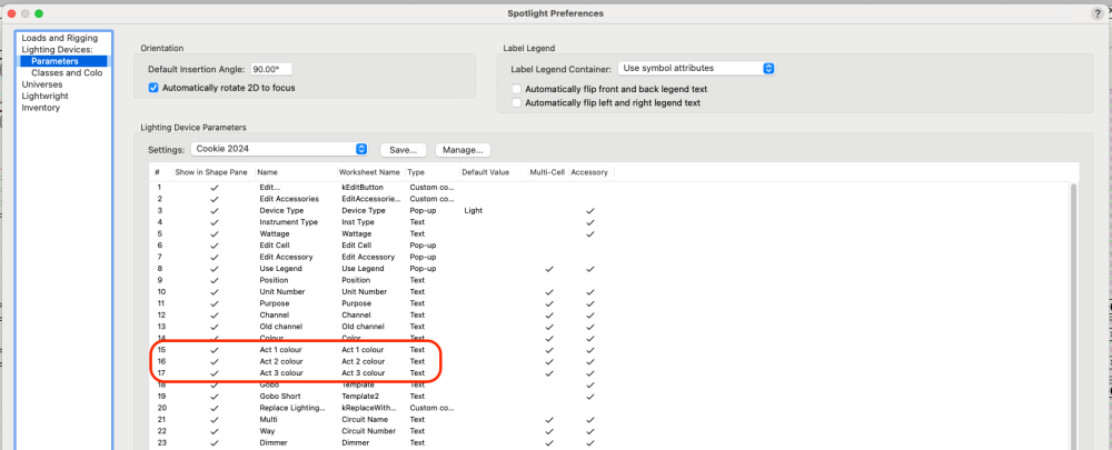
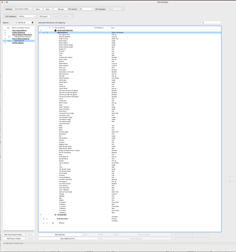
Hi all, I'm delving into the Data Manager for the first time. The task: We're working in Rep with different gels/colours/filters in lights for different acts of the same show. This informations needs to be displayed on the plan, as well as counted for prep. I've added 3 new parameters to the lighting devices in Spotlight preferences: Act 1 colour, Act 2 colour, Act 3 colour. I can use data tags to display this information in the plan. I was then going to use the data manager to combine these fields into the original colour field ('Act 1'+'Act 2'+'Act 3), so Lightwright would be able to produce a colour count. But the additional parameters do not appear in the Data Manager window when lighting device is selected Is it possible to get new lighting device parameters to show in the Data Manager, or are these fields not available? Or can anyone suggest a better way to tackle this problem? Any thoughts or suggestions most welcome! Cheers, Cookie
-
Hi Mark, Works like a charm! Thanks as ever. Cheers, Cookie
-
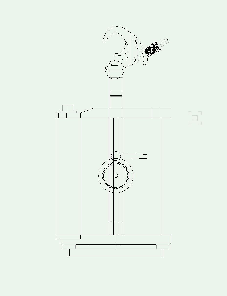
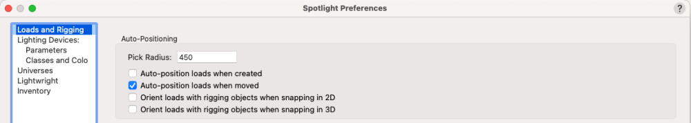
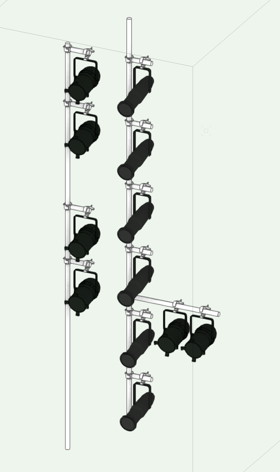
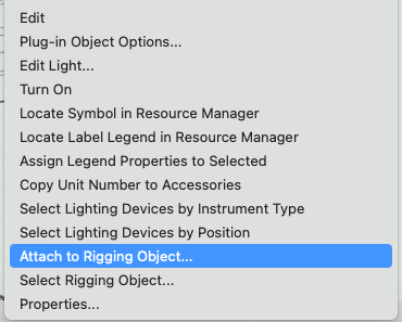
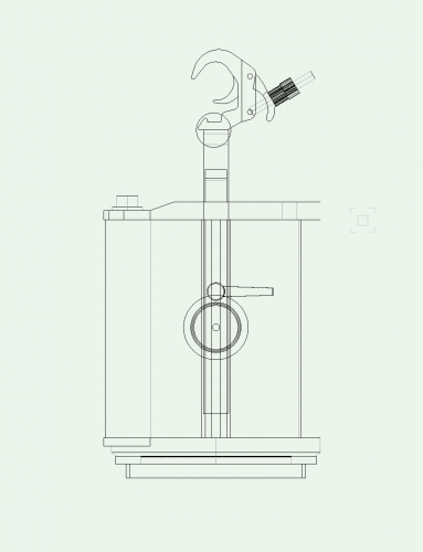
Is there a command/tool to attach a light to a hanging position without the lighting device snapping to the position? The Attach to Rigging Object... from the contextual menu will move the lighting device to the hanging position. I'm aware of the Auto-position settings in the Spotlight preferences: But these functions can cause the lighting device to snap to the wrong piece of geometry, particularly when working with booms/side lighting positions. The lighting device will snap to the vertical pipe and not the boom arms (the boom arms are Point loads in the drawing below): Cheers, Cookie
-
Graphic Legends as equipment summary - rotation of lighting devices
Cookie_NZ replied to Cookie_NZ's topic in Entertainment
Hi Mark, That's fantastically helpful information. Much appreciated. Cheers, Cookie -
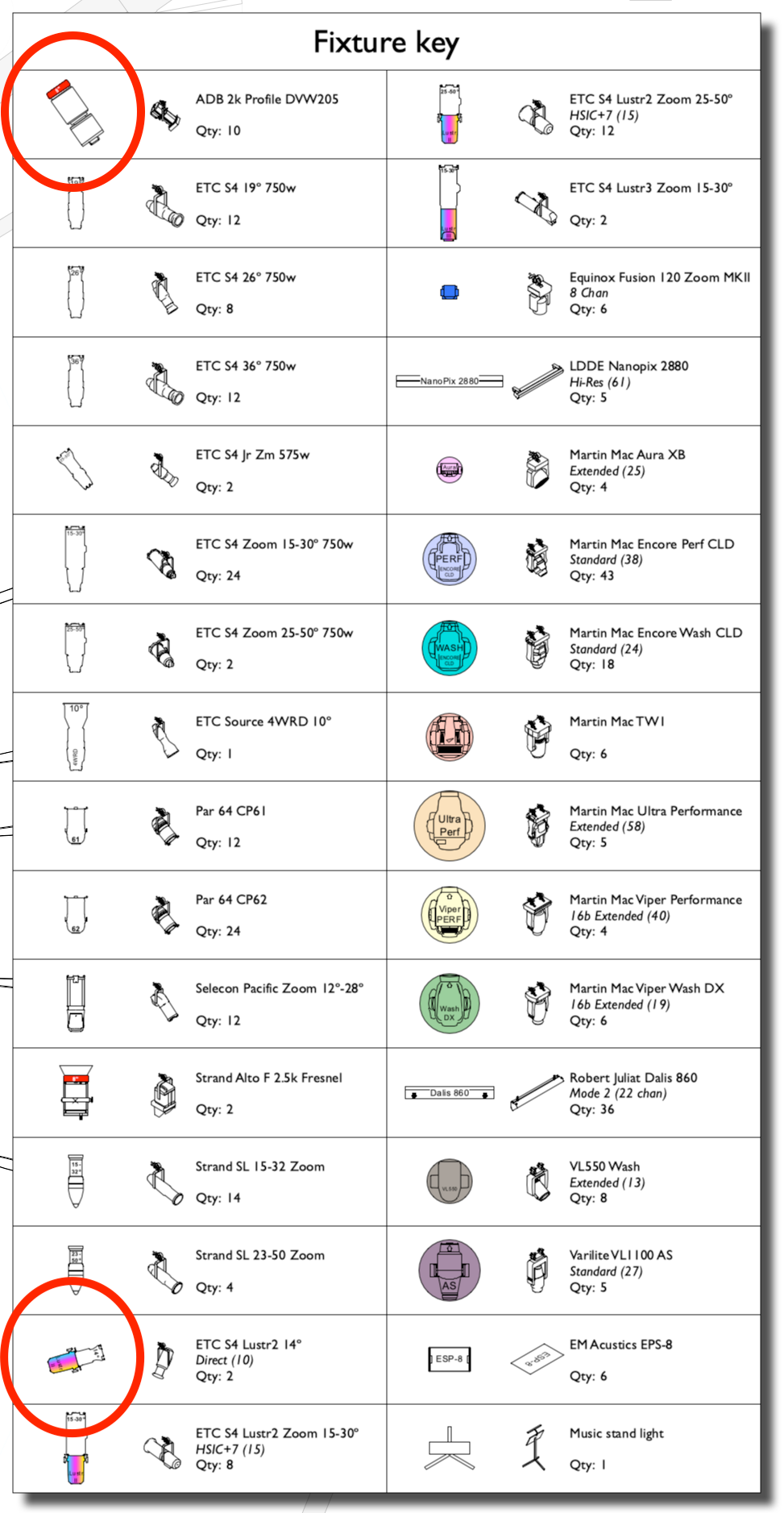
Hi all, I'm enjoying experimenting with Graphic Legends as an equipment summary. The legend image seems to select a specific instance of a lighting device to display. Some of my lighting devices in my file have custom plan rotation, so appear rotated in the graphic legend. Is it possible to force a graphic legend to ignore custom plan rotation? Or, is it possible to select a specific instance of a lighting device for the graphic legend to display? Cheers, Cookie
-
Versioned Vectorworks Icons - Updated Yearly
Cookie_NZ replied to MadXD's topic in General Discussion
Thanks @MadXD It's a little thing, but it makes me very happy! Cheers, Cookie -
Versioned Vectorworks Icons - Updated Yearly
Cookie_NZ replied to MadXD's topic in General Discussion
Hi @MadXD. Any chance of a 2024 update to these? I think they are the best thing since sliced bread.... Cheers, Cookie -
Editing 'Lighting Device.Z Location' field in worksheet
Cookie_NZ replied to Cookie_NZ's topic in Entertainment
Hi Pat, I've DMed you the file. Script compiles ok: I've tried 'Execute' & 'Always Execute'. Same behaviour. Cheers, Cookie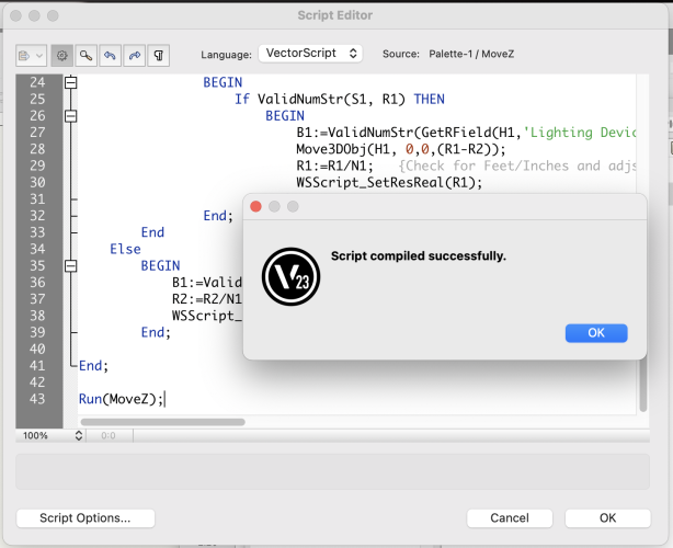
-
Editing 'Lighting Device.Z Location' field in worksheet
Cookie_NZ replied to Cookie_NZ's topic in Entertainment
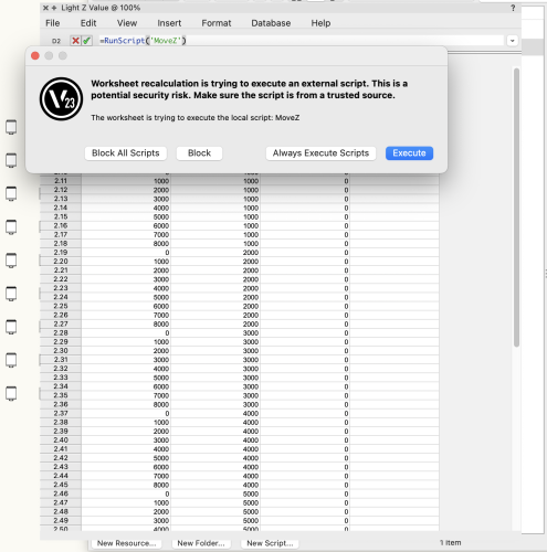
Hi @Pat Stanford bless you for your procrastination! Although I think I've fallen at the last hurdle. I've added the script to the file and =RunScript('MoveZ') formula to the worksheet. But I can't edit the 'MoveZ' row data. (Get a 'ping' error sound when I try). If you get a moment, would you mind taking a look at the attached file and let me know what I've stuffed up in the process? @TomWhiteLight Interesting that XYZ data cannot be edited from a worksheet. Do you know if this is a technical limitation, or a design philosophy choice? Cheers, Cookie Bulb height (MoveZ).vwx -
Hi all, I'm working on a project where we'd like to set the Z height of lighting devices from a worksheet. I made a worksheet with a 'Lighting Device.Z Location' column. But I can't seem to alter this value in the worksheet. Am I doing something wrong, or is this field not editable from a worksheet for some reason? Example file attached. Cheers, Cookie Bulb height.vwx
-
Hi Tom, Any chance you could share this texture? I'm playing the same game looking at bouncing light off multiple mirrors. Because I want to see lit fog for the reflected light, I think the only way currently is to cheat it. Your fuzzy glowing cloud sounds like it's worth a try! Cheers, Cookie
-
Focus settings for lighting devices - VWX Spotlight to Architect
Cookie_NZ replied to Cookie_NZ's topic in Entertainment
Hi all, OK, no problem. Good to get clarifaction! Thanks for the responses. Cheers, Cookie -
Hi all, I have a Spotlight file I've shared with a designer who is using Architect. In my file the lighting devices are all focused, but when the designer opens the file in Architect they are all pointing down. Is there anyway to fix this? Or is this a limitation of Architect? Cheers, Cookie
-
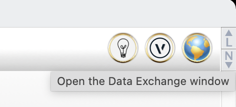
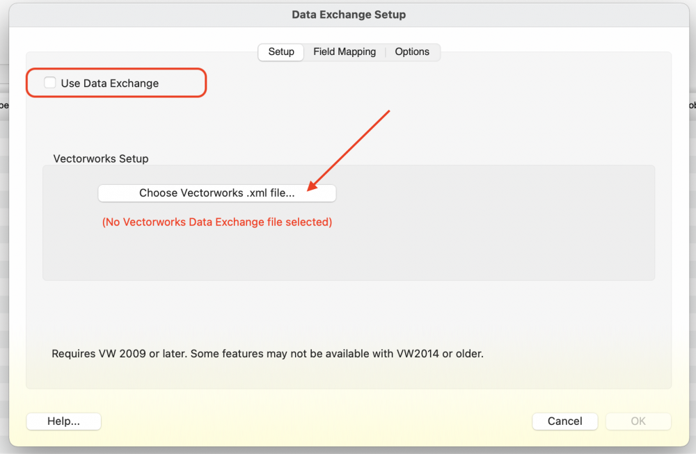
Hi @Milner Sommers, I think you might be using the wrong command to link Lightwright with your VWX file. 'Import Data' is used to import fixture information from a CSV or tab-separated file. To link your LW with your VWX drawing, use the Data Exchange function, which you access by clicking the 'V' Icon in the top right of the LW window: From this dialogue tick the 'Use Data Exchange' box, and then select the .XML file.
- 1 reply
-
- 1
-

-
Displaying referenced files in a title block or worksheet
Cookie_NZ replied to Cookie_NZ's topic in General Discussion
Brilliant, thanks Pat. -
Displaying referenced files in a title block or worksheet
Cookie_NZ replied to Cookie_NZ's topic in General Discussion
Hi Pat, Thanks for the reply. Sorry that was a VERY old signature, which I didn't realise was still there. It doesn't show in my posts to me when I view them! I'm on 2021 Designer. I'm using Layer Import references for this workflow. Cheers, Cookie -
Hi all, I'm looking for a way to display all of the referenced files in a document either in a title block or worksheet. Any pointers in the right direction would be much appreciated! Cheers, Cookie
-
Hi jcogdell, Brilliant, thanks for the information. I'll give it try. Wish me luck! Cheers, Cookie
-
Hi all, Could anyone share any tips on tools & process to model you own truss pickups with spansets? It's an interesting 3D modelling exercise that's currently beyond my skill set to do accurately. It would be great to put a set of symbols together to show the various wrap options, and what can be achieved with the set lengths of spansets available in the UK. Cheers, Cookie
-
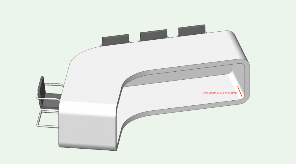
Hi all, What's the best why to shell a solid to a specific depth? I have a desk I'd like to create an indentation of 200mm to the front face, leaving 100mm of the desk structure all the way around. The shell tool does a lovely job of leaving the 100mm around the edges, but cuts all the way to the back of the object. Is there a way to limit this cut? Or of course a better process? Image below for reference: Cheers, Cookie
-
StudioScan offers LiDar scanning and CAD services to the broadcast and events industries. We’re looking to put together a pool of freelancers for Vectorworks drafting on upcoming projects. In particular those with experience in working with point clouds on architectural projects. If this interests you, please get in touch with your CV: cookie@studioscan.tv www.studioscan.tv
-
Hi @JustinVH, thanks for the clarification. I think where I was going wrong when pre-adding clamps was I attached the Lighting Info/Parts record to the clamp symbol after I had added it to the 3D geometry of the lighting device (from within the Edit 3D Component window for the lighting device). In this process VWX recognises the clamp as an accessory, but not it's correct placement for hanging on a lighting pipe. If I attached the Lighting Info/Parts record to the clamp symbol first, and then add it to the 3D geometry of the lighting device (using the symbol insertion tool), it's correct placement is recognised:

-
@JustinVH thanks for the explanation of the process to add clamps as accessories. I was having the same problems as @Mark Aceto Supplemental question: Can we pre-add clamps to lighting devices so they come in from the resource manager with the most common clamp for that lighting device already attached? Or if we're running clamps as accessories do they need to be added every time a lighting device is added to the drawing?