


RDS Casa
-
Posts
202 -
Joined
-
Last visited
Content Type
Profiles
Forums
Events
Articles
Marionette
Store
Posts posted by RDS Casa
-
-
ah, just found it. Sorry. Its in Document options, the last menu,
Thanks
-
Hello, could I ask how did you get the revisions to be P1, C1 etc? its automating to A, B, C for me.... is there an automate tick box I am missing?
Thanks
-
I understand the theory, but these are planning elevations for a very sensitive site... I can't risk going in with clunky drawings. If it changes after planning, I don't care about the subtle set of elevations - they will not be a construction set, are are not likely be used again.
For the construction stage, they'll be a ton of iterative changes I have no doubt, and there I will use the bim model. But at this stage, if my client changes it after sign off for planning, they can pay for me to change the drawings!
Thanks
-
Thanks, but I'm trying to keep it in the design layer, so I can convert to lines and then play with all the line weights and add little bits I've not modelled . I can't find a way to have this kind of render in the design layers view ports??
Thanks again for your time.
-
Just searching for the same answer.
I'm actually setting up sectional viewports in the design layers, then at the final stage, I take the hidden line renders, and covert copy to lines, and then monkey about with them to get a subtlety I can't get straight from the model with out putting loads of time into to it. I just find it quicker that way.
So I don't even have the option of background render setting in design layer viewports (...do I??). Ideally I'd turn on the shadows, trace them or even just see what happening on the complex stuff, then approximate them as a polygons with opacity. Does anyone know how to do this in the design layer viewports?
I know its not seamless workflow, but I can make simple models very quickly, and add all the detail manually. For me this is quicker, even if means the odd bit of reworking if things change.
Suggestions appreciated.
Thanks
-
Hey,
Yep, spot on, as soon as I moved the boundary to be over the loci, it worked just fine.
Thanks
-
10 years later I have this exact question. I added the 3d loci to the site data using edit source data... it does not work. VW2018 SP2.
Any suggestions?
-
Hello, I also have a site model subtraction question, which is how I have found my way here.
What if I want to build a tunnel, or a partially underground (with terrain on top) building in my site model? I have a building on a steep slope. Its partial recessed into the hill so the the entry level is the 1st floor, the ground level drops with the slope. This is simple and there are lots of good tutorials on it..... But, where the hill curves around, I need to send a tunnel so it pops out on the other side, i.e underground accommodation with terrain on top. Essentially the site model needs a hole through it?
Whats my best strategy? a conventional model using the pad with retaining wall site modifier, then put a mesh landscape lid on top (just a mesh object) ? or is there a tunnel modifier that I can't find?
Thanks anyone.
-
Ok, this would work. Also, you have made me think I can just copy and paste the script from the pass node, into the script for what ever node I'm replacing, then wire the new input node into the front end of this. I tried the copy and paste trick before, but if you try and replace a single output node, with a double output node, it really does not like it.
I never considered the using the pass first.
Thanks as always
-
Well I've got somewhere by hacking together a few nodes. This node provides a pop up, where if custom is selected, it defers to the input dimension. It also outputs a string associated with the choice made. But, if custom is selected, a value entered, then a standard option selection made later, it does not change the displayed custom box. Or grey it out
I don't know if this is possible, but its a start at least.
#fjs 19.12.17
@Marionette.NodeDefinition
class Params(metaclass = Marionette.OrderedClass):
this = Marionette.Node( 'Popup custom' )
this.SetDescription('The values returned set out in script')
input = Marionette.OIPControl( 'Popup', Marionette.WidgetType.Popup, 0, ['custom', '150mm', '200mm', '300mm'])
input.SetDescription('an OIP control representing the options designated within the script editor')
d = Marionette.PortOut()
d.SetDescription('The resulting value in document units')
dim = Marionette.OIPControl( 'Custom (if selected)', Marionette.WidgetType.RealCoord, 0.0)
dim.SetDescription('A numeric OIP control that accepts unit indicators')
string = Marionette.PortOut('string')
string.SetDescription('an string corresponding with the option selected in the OIP')
def RunNode(self):
units = vs.GetPrefReal(150)
input = self.Params.input.value
if input == 0:
self.Params.d.value = self.Params.dim.value/units
self.Params.string.value = 'custom'
if input == 1:
self.Params.d.value = 150
self.Params.string.value = 'standard'
if input == 2:
self.Params.d.value = 200
self.Params.string.value = 'standard'
if input == 3:
self.Params.d.value = 300
self.Params.string.value = 'standard' -
Hello,
Does anyone know an easy way to switch nodes with out rewiring? I have a increasingly complicated network. I need to switch out a real input to a slider for example. It might have 10 wires coming out the back.
Thanks
-
Hello, is there any solution to this? When I try it on another file, I can get a worksheet to drive record data, but this does not push through to the marionette object parameters? So If I change it in the table, it changes the record and field data, but then the height (for example) in the data tab, just becomes inconsistent with the shape tab.
When I change the shape data, it does indeed override the record data again, so its definitively one way... did anyone find the 2 way more involved solution? Is it possible to put in an update button on the object? to get data back from the worksheet?
-
Ah, awesome. Thanks
-
Strange. Try this.
Is it a 2017 thing? many jobs here are on site and are in 2017, and we really don't want to convert if we don't have to. I know they say its fine, but sometimes it isn't (been there before). New projects are starting or converting to 2018, but not the ones on site
Thanks.
-
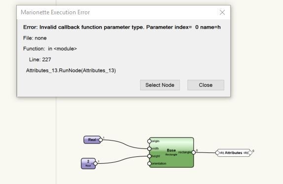
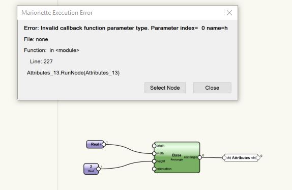
I have some networks in 2017, so without the valve node. They are working, but all I need to do is set the attributes of the objects. But when I use the attributes node, and the shape never gets made, it gives an error command. I assumed this was because there was no object to apply the attributes to?
This can be recreated quickly with a simple rectangle node. Attach inputs to width and height, then put the attributes node at the end. All fine if the inputs are 2 and 3. But if an input becomes 0, and the rectangle does not get made, it returns an error and identifies the Attributes node.
Thanks for your help as always.
-
Thanks @Alan Woodwell
So the Max item on a double if can work like a If this OR that true, then true, if both true then true, if both false then false ? neat trick.
I tried using your
if self.Params.obj.value != vs.Handle(0):
extra in the attributes node, to stop the node falling over if something is not there.
On 05/12/2017 at 1:50 PM, Marissa Farrell said:This states
"If the object passed is not an empty handle (is a handle), then delete this object."
This prevents the node from trying to delete information it can't, and prevents the script from running if the value is not of the correct type.
Can it work in this capacity at the top? Where am I going wrong? I added the python 4 space indentation to everything below it?
def RunNode(self):
if self.Params.obj.value != vs.Handle(0):
if self.Params.IN.value != 0:
h = self.Params.IN.value
if vs.IsFillColorByClass(self.Handle):
vs.SetFillColorByClass(h)
else:
vs.SetFillBack(h, vs.GetFillBack(self.Handle))
vs.SetFillFore(h, vs.GetFillFore(self.Handle))if vs.IsFPatByClass(self.Handle):
vs.SetFPatByClass(h)
else:
vs.SetFPat(h, vs.GetFPat(self.Handle))if vs.IsLSByClass(self.Handle):
vs.SetLSByClass(h)
else:
vs.SetLSN(h, vs.GetLSN(self.Handle))if vs.IsLWByClass(self.Handle):
vs.SetLWByClass(h)
else:
vs.SetLW(h, vs.GetLW(self.Handle))
if vs.IsMarkerByClass(self.Handle):
vs.SetMarkerByClass(h)
else:
ok, style, angle, size, width, thickBasis, thickness, visibility = vs.GetObjBeginningMarker(self.Handle)
vs.SetObjBeginningMarker(h, style, angle, size, width, thickBasis, thickness, visibility)
ok, style, angle, size, width, thickBasis, thickness, visibility = vs.GetObjEndMarker(self.Handle)
vs.SetObjEndMarker(h, style, angle, size, width, thickBasis, thickness, visibility)if vs.IsPenColorByClass(self.Handle):
vs.SetPenColorByClass(h)
else:
vs.SetPenFore(h, vs.GetPenFore(self.Handle))
vs.SetPenBack(h, vs.GetPenBack(self.Handle))if vs.IsTextStyleByClass(self.Handle):
vs.SetTextStyleByClass(h)xOrigin, yOrigin, xIAxis, yIAxis, xJAxis, yJAxis = vs.GetFillPoints(self.Handle)
vs.SetFillIAxisEndPoint(h, xIAxis, yIAxis)
vs.SetFillJAxisEndPoint(h, xJAxis, yJAxis)
vs.SetFillOriginPoint(h, xOrigin, yOrigin)if vs.GetOpacityByClass(self.Handle):
vs.SetOpacityByClass(h)
else:
vs.SetOpacity(h, vs.GetOpacity(self.Handle))
self.Params.OUT.value = self.Params.IN.value
-
Hello,
I'm trying to create a marionette object that has similar input method to the steel section tool in VW. Here you can select from a series of default sizes or options, or you can tick a custom boolean, and input the parameters yourself. In the steel tool, the choices are greyed out without the custom boolean ticked. This would be ideal, but I think I read the the OIP can't change like that in an marionette object? If it can't do this, is there a way to override preset choices in a similar way?
am I going to need 2 objects, a standardised one, and a custom one?
Thanks
-
Thanks so much, I'll go through these next week. Your previous post have been absolutely instrumental in helping me progress through marionette, so I'm rather excited about going through these!
Thanks again for all your posts, they have been fantastic.
-
Thanks, I'll take a look next week.
Thanks again
-
ah, I am actually using 2017, sp4. I've now down loaded 2018 and will install tonight. If its a bug, while frustrating, it makes me feel a bit better as its not the way I built them. Thanks so much for the prompt reply. I'm going to try and find a way to definitively reproduce the issue, and will then post a screen cast or something.
Indecently, ultimately I think I might take the marionette objects, covert the wrapper to a python script, then using your fantastically helpful video https://www.youtube.com/watch?v=bBiai3iD-W0 (thank you again by the way), convert them into a plugin point object. I seem to have more control on the OIP display this way, and I think it suits what I'm trying to do better. I don't suppose you know the nature of the bug above? and whether this convert to plugin object method might ultimately stop it?
Thanks
-
Hello,
I'm getting some strange behaviour on some marionette objects I've made (but please understand I'm new to this). They are simple objects, made from extruded rectangles. Sometimes, when I play with the parameter slider bars, the objects randomly jump position. Its as if they are jumping back to the origin. Then when I change something unrelated to the script, say the fill of the object, they will jump back.
Some of the origin inputs of the rectangles have a small positioning translations to put them in the right place, but these all calculate back to a default 0,0 origin (i.e. I've not defined any origin). I.e. there is no defined insertion point like in a symbol?
Then, sometimes when I go into the script, come out, it jumps position again?
Most frustrating is its inconsistent, Some time I can't get it to do it at all?
It might be a display issue. I.e. when I make changes, it displays the object somewhere else, then, at some seeming random point it updates, and moves it back to where it really is?
Has any one else experienced this? Is it the way I have built it? Is there a way to tie it all to an insertion point? or something to do with the display settings?
I've not messed with the user defined origin in these files, so it should be the same as the real origin.
Thanks for any help
-
Hello, this was posted 2016. Any further advice on the button node? any examples? DomC video moves pretty quick for me! I can't really follow it . What I'm really hoping for is a way to get the button in the OIP for a marionette object, so it maybe just brings up a text box with guidance or a web link?
Any ideas?
Thanks.
-
Thanks
-
Actually I do have a very quick question: If I had a marionette object, with a valve node from 2018, and I tried to put that object into 2017 for others, I'm guessing it simply would not work?
Thanks
Arcs to circles.
in Marionette
Posted
Hello,
I have some files which are apparently full of circles on different layers and different classes... but actually the circles are made from 2 or more arcs
I need these to be actual circles - fully closed circles with a centre point.
A first search of the forums bought up this
with more brilliant contribution by @Pat Stanford
Which almost does what I need, but to be honest I could not get it to work at all, maybe it needs a certain type of data? but it did not work on my arcs.
So I've turned to marionette.
So far, I have a simple script, it works on a basic level, but raises some marionette question I can't answer. Please see attached.
Problems:
1. : It applies it to all the arcs in the drawing, across all layers and across all classes, even if I restrict to show/snap only etc, even if the layers are turned off.
I introduced a >get class >set class chain, and this at least keeps the new circles in the same class. But I really need to restrict which classes the script runs on. Is there an easy way to do this? if it only applied to the active class, I could work with that, but ideally I could input the classes which it would be applicable to in the OIP?
The same is kind of true to layers... It applies it to all layers, then dumps the new objects in to a group on the current layer?
I made a modified "set layer V2" node" which does not seem to work... because I hacked it and I think I'm missing a step. please take a look. Ideally, just like the Set class chain of nodes, it would keep the layers as per parent object? but even if this does work, it throws everything into a group in the current layer, Can this be stopped? Alternatively, how do I restrict the the script to only the active layer, as this would be ok.
Can you add multiple criteria to the "Object by Crit" node? T must mean type? i.e. T=arc picks the arcs, but is there list of other selection criteria?
These other questions below are less important for my current task, but I'd still like to know how?
2. The class >get class>set class works fine, but is there an short hand node that gets all the class attributes, and sets them all to the new object, with out going through line colour, fill colour etc opacity etc in individual nodes? to be honest this is not as important as problem 1. But I was interested in the answer.
3. Even when this is working, because the original file has circles made from 2 arcs, it will place two circles in the same place. Is there an easy way to delete the same geometry which lies on top of each other in the same layer and class? Again, this is a nice to have options for neatness. Problem one is the urgent one.
4. Finally, the file contains a number of shapes I need as closed polylines. Currently they are all lines and more arcs. which when I modify>compose almost joins them together. Sometimes it does, but most times they are 2 or 3 ploylines. I suspect that this is because if I were to zoom right right right in, they might not touch... Any easy solutions or suggestions here?
Thanks everyone.
Rob
arcs to circles.vwx