


JBenghiat
-
Posts
2,028 -
Joined
-
Last visited
Content Type
Profiles
Forums
Events
Articles
Marionette
Store
Posts posted by JBenghiat
-
-
You need to use HMove3D() to set the height after inserting the symbol
-
 1
1
-
-
22 hours ago, FMA said:
This might be a little bit complicated to get around. Is there any way to activate a tool with a key stroke, or to get access to the normal program functions during a loop? Would be great if anybody knows if that is possible. I can share the whole code if needed.
No, not in Vectorscript
-
1
-
-
Thanks Andy and Sam! ProjectionViz 2 will rotate the projector to the tilt and generate the hybrid Top/Plan view. It will also let you choose the floor plane for visualizing the projector cone (as well as correctly displaying key stoning and lens shift). The Video Screen tool is going to give you a lot more options for showing the details of the projector mount and screen, while ProjectionViz is more targeted towards planning and visualization. It is currently Braceworks but not ConenctCAD compatible.
https://benghiatlighting.com/software/product/projectionviz-2/#description
-
1
-
-
This would be fairly straightforwards to script. I would use python in order to take advantage of built-in list functions. Perhaps obviously, all the lighting devices would need to be in the same layer for the stacking order to apply to the full range.
- Use ForEachObject() to build a list of Lighting Devices, with a dictionary holding the handle and channel number
- Sort the list by the channel
- Iterate through the list, using HMoveBackward() on each handle
Alternatively, the mvr file is just a zip that contains the plot as an XML file. You could write a python script that sorts the XML entries by the FixtureID element. That's probably something ChatGTP could handle.
-
2
-
-
I feel like with criteria, you can never have too man parentheses, but at least the outer-most set is redundant.
You don’t need more quotes than with vs, so just record and field names, object names, etc. Should have single quotes.
-
1 hour ago, Pat Stanford said:
But Looking at the ForEachObject sample code on the developer site it looks like you may need to use quotes in Python.
In Python, the entire criteria needs to be a string
-
1
-
-
In this case, I think you can just increase the conditions under which you would select the object: OjbAngle == Rotation or OjbAngle == Rotation + 180 or OjbAngle == Rotation - 180
-
Just flagging that this is in the VectorScript forum, but your code is in Python. This is one of the few things that VS does more easily: you can just specify units, i.e. CreateShell(h, 2”).
In Python you have to do unit conversions. vs.ValidNumStr is the most robust
https://developer.vectorworks.net/index.php?title=VS:ValidNumStrJust to throw a wrench in things, I believe some functions always take millimeters, and this may be one of them. Best practice there is to retrieve the units per inch preference, and convert input numbers into millimeters.
-
1
-
-
You can use data tags to individually label each piece of truss.
My Savvy Position Label tool allows you to summarize the components of a truss system or truss line: https://benghiatlighting.com/software/product/position-label/
Also look at the truss tags in Sam Jones’ AutoPlot:
-
3
-
-
I developed Savvy Select Similar Instrument for exactly this purpose. The Select Similar tool doesn't access specific Spotlight data: https://benghiatlighting.com/software/product/savvy-select-similar-instrument-3/
-
2
-
-
It depends a little bit on what the objects are. If they are parametric geometry, the cleanest and fastest results will be to calculate the top view and draw it.
An Autohybrid is just a PIO with the 3D geometry in its profile group, so you could place an Autohybrid to take care of the 2D component.
You can get the best results from vs.Generate2DFrom3DComp. https://developer.vectorworks.net/index.php?title=VS:Generate2DFrom3DComp That requires your objects to either already be symbols and PIOs or to place your 3D geometry inside a temporary symbol or a NNA_TransformGroup PIO, but that requires a bit of longer explanation than would be suitable for the forum.
-
1
-
-
7 hours ago, Slaterade said:
If I understand your answer, then this is what Im trying to avoid. I have built plans before where there is a small mini 'locator' plan, and then a box that shows a blown out version, but this is not what Im looking for here.
Effectively, I want to display a ground plan at a 1:100 scale, but with the lighting instruments (and their label legends) at x2 scaling, and therefore producing a drawing where layers are different scales to each other but shown on top of each other.
This is the answer — what you really want is two sets of viewports — one that shows the overall ground plan, and one for the lights. By best drawing practice, the "locator" plan would show a footprint of each light, with a larger version of the symbol and label legend. Having two scales in one viewport would violate the idea of drawing in scale — setting the lights to be 3x larger would also make them 3x farther apart. You CAN scale text and page-based symbols using the viewport's Advanced Properties towards the bottom of the OIP, though this applies to all text in the viewport and the symbols in Lighting Devices does not scale.
Many don't know that the clip tool works on viewports. To achieve the dual plans quickly, I would:
- Copy and paste-in-place the ground plan viewport
- Change the viewport's layer settings to turn on the lights and turn off the ground plan
- Set a class for the viewport to make it easily selectable later, e.g. VP-Lights
- With the viewport selected, use the Clip tool in the third, Split, mode to draw a marquee around each light or group of lights
- Delete the now empty, surrounding VP (it should have a bunch of holes in it where you clipped out the lights)
- Use the Select Similar tool to select all the VPs in the VP-Lights class
- Change the scale of the selected viewports
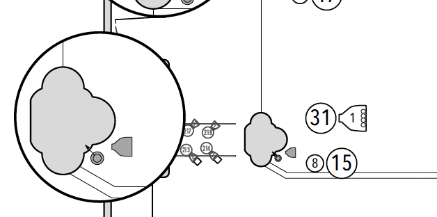
The example below shows the plan at scale, a scaled up VP with the border visible to show placement, and a third cropped VP at an even larger scale for the lights.
You could alternatively make a set of symbols and label legends with larger versions, and even toggle between sizes using classes. While you can set Vectorworks to scale a symbol in Object Info, Lighting Devices extract objects from symbols rather than insert them whole sale, so unfortunately you can't create two versions of the light that refer to the same geometry — you would have to edit the symbol, copy the 2D geometry, and scale.
-
1
-
And if you need to return from a 3D view to top/plan, you can also set the projection:
https://developer.vectorworks.net/index.php?title=VS:Projection
Alternatively, you can use vs.VSave/VRestore/VDelete() to save the current view and restore it at the end of the script.
You can also use SetPref(9873,TRUE) to prevent a screen redraw when the view is changed but then you MUST call SetPref(9873,FALSE) after you set the view back. You will see the largest speed increase in a 3D view from this.
You may also be able to avoid changing the view by setting the planar ref ID to a plan in the orientation you want. (Assuming you're changing the view to perform an extrude)
-
1
-
-
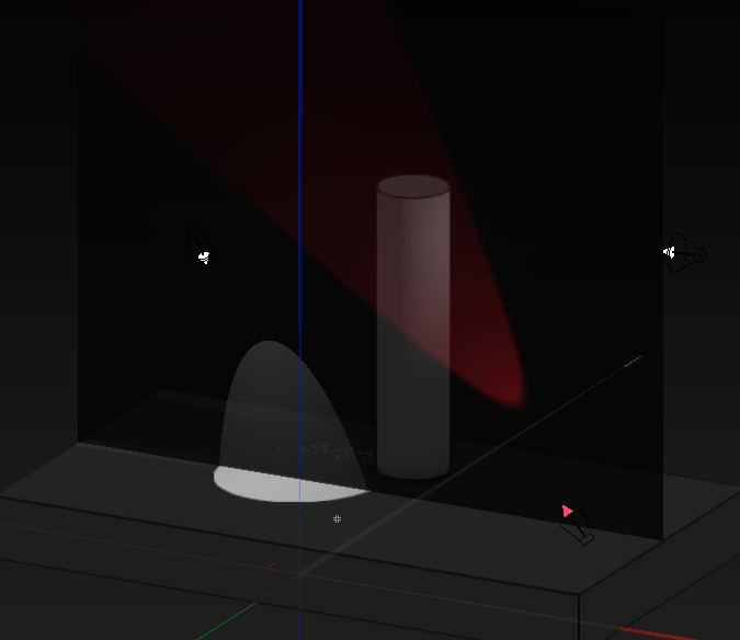
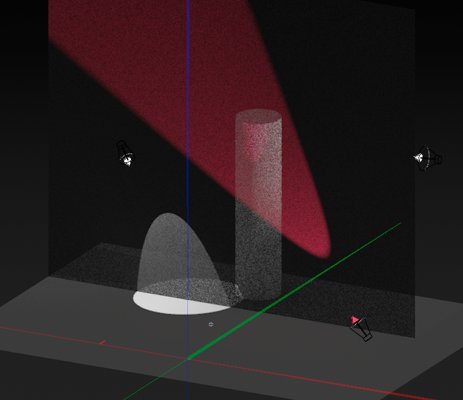
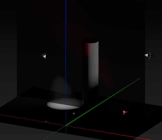
Here's an example of generating a texture in Substance and rendering in Shaded, Renderworks, and Redshift.
The Base Color, Opacity, and Bump shaders map to Color>Image, Transparency>Image Mask, and Bump>Image in Vectorworks. As you can see, render mode and settings can have as big an impact as the texture composition.
-
2
-
-
Vectorworks has a built-in texture called vsScrimTexture that uses noise transparency and bump shaders to approximate a sharks tooth scrim. The best solution, however, depends on what you are trying to accomplish.
I recommend thinking about whether you are creating a simulation or a presentation. If you are constructing presentation renders, the simplest solution would be to have two textures with different levels of plain transparency, and use viewport class overrides to render the bleed-through.
Simulating a scrim has its limits. If, for example, you're trying to determine the best front light angle to make the scrim opaque, you will probably have some difficulty finding a texture that has the subtlety you need. If you're rendering a bobbinet, using the tile transparency and thread reflectivity can have decent results.
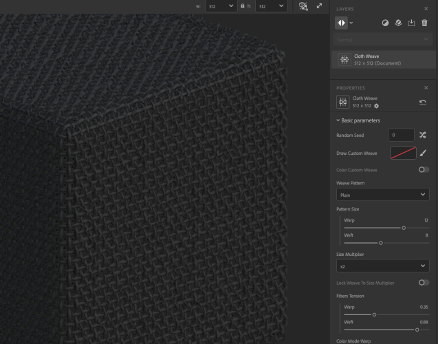
If you're exporting to a visualizer, you may need an image-based texture. I highly recommend Adobe Substance 3D Sampler as a way to generate textures. You can use it to generate an image-based transparent grid that blends seamlessly.
-
1
-
-
The simple answer is that GetCustomObjectInfo() returns the handle to the running PIO as the THIRD parameter, so you want:
PIO_handle = vs.GetCustomObjectInfo()[2]However, I recommend an number of additional considerations:
PIOs actually save their parameter data into a record, which is accessible from worksheets and scripts, so depending on what you are trying to accomplish, this may be an unnecessary step
Before attaching the record format, you should check to see that it exists in the drawing, and if not create it.
Attached records persist through object regeneration, so instead of attaching each time, you should first check if the record is already attached. I recommend using Eval for this.
SetRField expects a string as the value. I'm not sure if the rules for python are less strict than Vectorscript, but if so, and the record uses a dimension field, you'll want to use Num2StrF()
-
1
-
-
No — Python can’t run in the background and could only be triggered from the circuit object code. You need the SDK if you want to implement a listener.
-
1
-
-
The texture should have cast shadows enabled. That’s what makes them block light. Prior to 2023, Shaded/OpenGL would not account for the shadow cast/receive options in textures. Objects cast shadows by default as long as shadows are on in the render options.
-
1
-
-
The technique of acting on selected objects is what is giving you trouble. Selection status is really just a flag, so objects inside symbols can maintain their selection status, but not be directly editable (if you were to manually edit the symbol, you would then see those objects selected).
Any operations beyond basics should be done via handles as opposed to selected objects. In this case, you want to traverse the drawing structure, not just act on selected objects. Using @Jesse Cogswell's ForEachObject will work, as well the similar ForEachObjectInList. You can find several use examples as well as discussions of working with handles in the forum archives.
-
1
-
-
Time’s arrow flows one direction, unfortunately. You can migrate a VSM forwards, but not backwards. Your only option is to re-create the plug-in in 2023. Any updates you make in 2023 you can migrate to 2024 by copying the plug-in.
if you use external includes for your code, both versions can include the same text file and stay up to date.
-
2
-
-
Hard to say for sure, but that looks like an empty viewport — layer or class visibilities are set such that it has no objects to display.
-
1
-
-
Non-modal dialogs aren't possible in Vectorworks at the moment, so the request would need some scaffolding.
I'm also going to take a moment to shamelessly plug the sequencing features of Savvy Select Similar Instrument. You can use the mode bar keyboard shortcuts in conjunction with the tool to very quickly select and number units. https://benghiatlighting.com/software/product/savvy-select-similar-instrument-3/
-
1
-
-
You are correct— encryption substitutes a token for all the variable and constant names, so the value passed to the VSValue isn’t valid. The string repository commands (RepStr) will work, however, both for passing data between vs and python as well as for preserving data between script runs.
-
3
-
-
A number of potential issues, and some confusion about your description.
Screen plane objects don’t appear in 3D views. The only place where you will currently find screen plane objects is in hybrid symbols and PIOs, and because you only see the 2D component in top/plan, you aren’t really aware of the screen plane. If you are seeing a planar object in a 3D view, it’s in the layer plane or another 3D plane.
CreateTaperedExtrude appears to be essentially deprecated. Use CreatTaperedExtrd2.
Just going by memory, but I believe that when you create an extrude, the profile becomes part of the extrude without creating a duplicate. I believe what you are seeing is the object not having a 2D component, so you are only seeing the 3D in both views.
SetPlanarRef only works on 2D objects ( the 3D object exists in non-planar space). Because the extrude call returns a handle, it’s possible that LNewObj() still refers to the oval.
In the PIO code, all planar objects get created in the screen plane, so an extrude will give the object depth from the current view. Therefore, you DO need to set the planar ref (usually the layer plane) for all planar objects BEFORE extruding.
HTH

How to place a symbol at a specific height
in Python Scripting
Posted
Yes, sorry, I was going purely on memory. vs.Move3DObj() is the call.
https://developer.vectorworks.net/index.php?title=VS:Move3DObj
If you're not familiar with the concept oh handles, you can find a few threads here and on the Vectorscript forum. You would get the handle to the symbol with vs.LNewObj() and then pass that to the move command.