


Sam Jones
-
Posts
1,191 -
Joined
-
Last visited
Content Type
Profiles
Forums
Events
Articles
Marionette
Store
Posts posted by Sam Jones
-
-
It looks like the truss you need is in the Vectorworks libraries.
-
In other words add the insertion point X,Y to the control point X,Y.
-
 1
1
-
-
Thanks so Julian. I know I have never seen that SetObjProp call before, nor have ever seen one called inside another call. Cool beans.
-
I remembering there being a way to keep the default OIP from appearing when the first PIO instance is created. I can't find it. Did I remember incorrectly? If not, what is it? :-)
TIA,
-
I'm not sure this is the place to go into detail about 3rd party scripts. I'll try to keep it short.
1. The AutoPlot(AP) version you were working with is up to date.
2. You cannot use VW cable objects with AutoPlot Cable Tools. This is because there are many things going on besides putting data in Lighting Device fields. All 4 cable objects had to be enhanced to accommodate user definable inventories, box cable counts, and loom reports. Also implementing date functionality into cable tools required some changes. So... if you want assigning multi, jumper, and data cable info to Lighting device fields to work, you need to only use AP cable objects. AP cable objects can reside without conflict with VW cable objects, but those VW cable objects will not be recognized by AP commands and functions. There are commands to convert VW cables to AP cables but those conversion commands will convert all the VW cables in the document.
3. Using Project Sharing with AP Cable Tools is possible but challenging. The challenge is primarily with where inventory XML files reside. They need to reside in each user's User Folder, inside that Plug-in Folder. This can create challenges with keeping those inventory files up to date across computers. Later in August I will be investigating how to broaden the choices for inventory location.
There is a great deal to discuss about using cables in entertainment planning and drawings, but those discussions should probably be informed by the conversations I have had with production electricians, tech. directors, and corporate LDs over the last 2 years.
-
1. What AutoPlot Tools version is listed in the Registration menu command?
2. Send me the file.
3. include your phone #.
Sam
sjones@autoplotvw.com
-
Actually -2 works just fine. The problem was a "/" instead of a "\" in the XML element description. I later ran into a problem with a space in the XML element name. However, you should know that accessing the User Folder's Plug-ins folder is easily done with the GetFolderPath(-2). I do it all the time.
-
I am trying to write an XML file with the procedure
result := WriteXMLFile(hXML, -1, XMLFilePathName);
Unfortunately, the result is equaling -1028
result = -1028
1. What does -1028 mean?
2. Is there s list of the error codes generated by file creation and specifically XML file creation
TIA
-
Is there a way to get the path to a workgroup folder?
-
You're right I've never seen these, but they seem to be what we would call distros.
For now they will need to be objects not part of the VW cable universe but connected to it
Each object, I assume symbol, can have the record you show connected to it, and you run VW cables to them and from them. How you do this has a little wiggle room, but I would do the following.
For the 3x20, top picture:
I would run a 60 amp jumper cable to it and 20 amp jumper cables out of it.
For the 4a box, middle picture:
I would run a "5 wire, multicable" OR "single insulated conductors" to the box. Both need to have the appropriate phasing, wire gauge, and connectors selected.
This brings up the issue of "2 phase" service. How does that work? You show 5 wires which we would take to mean "3 phase" service. If you really mean "2 phase" service, then you are screwed, because that is not in option with VW cables.
Assuming all is good with the input I would run 60 amp jumpers out of it.
For the T-Towers, bottom picture:
I would run "5 wire, multicable" OR "single insulated conductors" to the tower and 3 separate runs of "5 wire, multicable" OR "single insulated conductors" out of the tower.
Do you need more?
-
1
-
-
Can you send me a drawing that has those objects and their custom records. This might end up being a phone call situation, but let me take a look first.
Sam
sjones@autoplotvw.com
-
1
-
-
I'm having some problems with what you show.
1. I do not see the blue control point for moving the label.
2. your stock lengths are in meters but you are displaying imperial in the cable and its OIP.
Can you attach a file that I can look at?
-
If the silly circles are attached only to multicable, then you need to find the check box in the OIP that is labeled "Draw Breakout Range" and uncheck it. It can be found below "Break Out Length". If the silly circles are occurring elsewhere, we'll need a picture, because I have no clue as to what you're talking about.
HTH,
Sam
-
1
-
-
First Question: Near the bottom of the Object Info palette (OIP), under the "Display On Drawing" separator is a check box labeled "Lock Labels to Standard Positions". Uncheck that box, and a blue control square will appear over each label. You can move the labels using those control points using the Selection tool (the arrow).
Second Question: I'm not sure why some cables have circles at the end and some do not. They all should be one way or the other if you have not done any manipulation in the OIP, but here is what the circles are about and how to get rid of them. When you lay any cable run, it can be divided into parts. A 150' cable will usually be divided into a Part 1 being 100' and Part 2 being 50'. There are other ways it can be divided if you want. The circles will mark the end of each part. In your case, you only have one part so the end of part marker is drawn at the end of the cable and is not very useful. You can turn off the display of the end of part markers by going to the same area as above and finding the check box labeled "Mark Connections". If you uncheck that box, all the circles will go away.
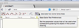
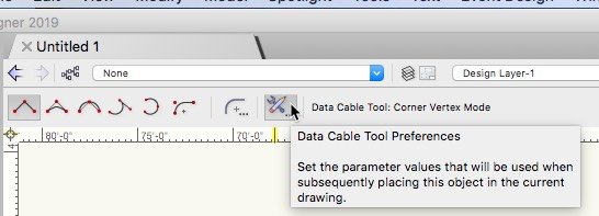
You can determine whether the default to check a box or uncheck a box by selecting a cable tool and clicking on the box below the class list that has a wrench and a pencil in it.
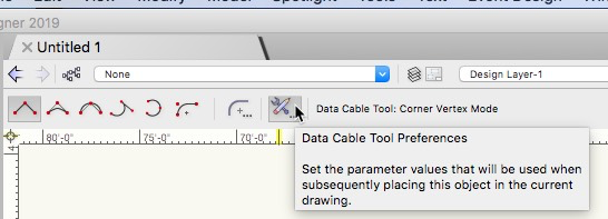
This will bring up the default OIP, and any settings you make there will be the defaults for that cable tool.
Third Question: You can adjust the shape of the arrow heads by assigning the cable run to a class and adjusting the class attributes. You can only adjust the shape of the circles by changing the shape of the "Cable End Marker" symbol. If you modify the symbol in your working file, it should change the that shape in that file. However, all new files will import the symbol from the "Marker Symbol" file. On a Mac, that file is located in the "Marker Symbol" folder located in the "Cable Tools" folder located in the "Defaults" folder located in the "Libraries" folder" located in the Vectorworks 2019 folder.
HTH,
Sam


-
1
-
-
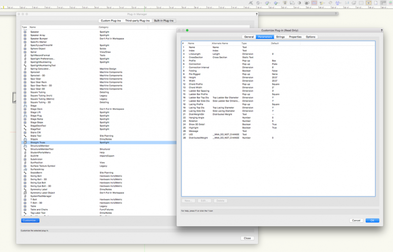
I have a friend who is trying to edit the defaults of the Straight Truss using the plug-in manager. When he gets to "Customize Plug-In" dialog it is titled "Customize Plug-In (Read Only)". I am not seeing this on my machine and have never heard of it. Does anyone know what might be causing this?
TIA
-
Scott,
I'm cruising the inside passage on a smaller vessel with limited internet, but you could use the AutoPlot "Place VLM Truss Tags" command. You can delete the tags if they are no use to you, but they will leave the HP truss with a position field attached to the Truss Record and filled out with the HP name.
Josh pointed me in the right direction, but sorting out the multiple Truss Records had some trial and error involved in order to find the correct one to consistently use.
-
 1
1
-
-
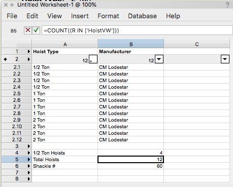
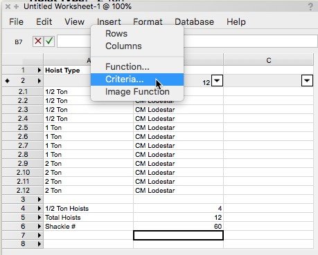
The worksheet function "COUNT(criteria)" can count things with the same symbol name, same attached record, same value in record field, or a host of other criteria.
in the worksheet screenshot below
In Cell B4
=COUNT(('HoistVW'.'Type'='2 Ton'))
will count all the Hoist plug-in objects that have the value "2 Ton" in the "Hoist Type" field.
In Cell B5
=COUNT((R IN ['HoistVW']))
will count all the Hoists.
In Cell B6, is your formula for Shackle # which is =B5 *5
You will need to get familiar with the criteria for formulas. This is most easily done by going to the insert criteria menu in the worksheet "Insert" menu

This will bring up a dialog:

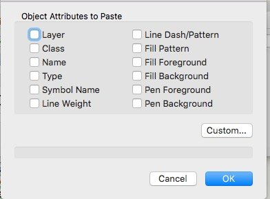
Click on the "Custom..." button, and that will bring up a dialog:
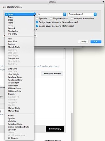
You will almost always want to pick Record or Field value from the left hand drop down, but there are occasional times when you will pick other criteria. I don't have the time or expertise to write the book on worksheets of VS criteria and functions, so you will have some research to do. Pat Stanford who prowls all corners of the of this list is the current non-VW employee expert on worksheets. You should get answers to the various questions that come up for you.
Have fun.
-
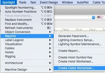
To get cable counts, you would need to layout your cable runs with the 4 cable objects and then go to:
None of this loads the results into the kind of worksheet you describe, but it may be copied into Excel.
-
The X and the The quick answer is no. However...
You can click on the "Set Hoist Data Display..." button in the OIP of the Hoist and choose to display the X and the Y, but that won't save you much. To get exactly what you want, I'm afraid your stuck with typing it in.
To a more philosophical thread, a simple xxx, yyy might suffice for you and, that's great, but considering the many different origins one can measure from in most cases, the current display is the most efficient and clear, at least according to the scores of riggers that beta tested it. Identifying the direction of the origin is crucial and allows different hoists to measure from different places.
-
1
-
-
5. Josh, Carlotta, Raymond, Matt, and you
-
Is there a way to retrieve the length of a 3D Poly? Do I have to get the vertices locations with GetPolyPt3D and then compute the distances between them?
-
The flow charting tools are cool, but for even "quick&dirty" cable plans, I don't think there as convenient or as powerful as Spotlight's cable objects.
-
I have a tool that places a point object after a click on an already existing object. I would like to use TrackObjectN to filter the target objects. All well and good except...
TrackObject does not start highlighting acceptable objects until after the first click. Does anyone know how to trick it into starting to highlight objects as soon as the tool is selected?
-
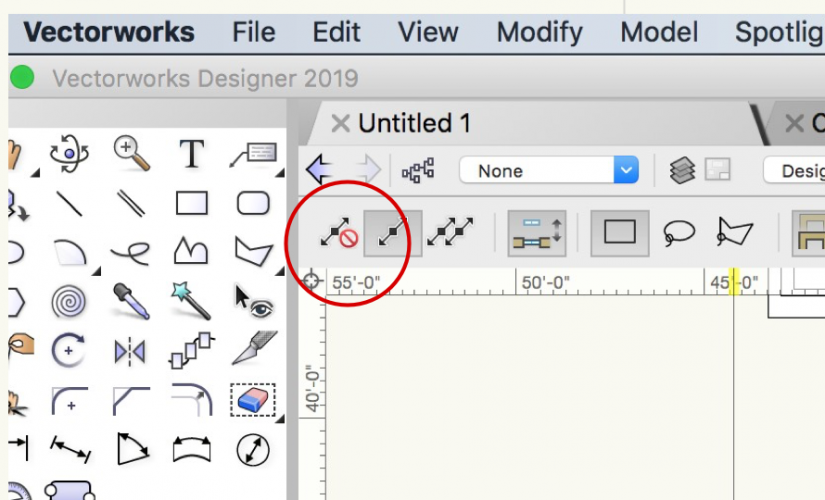
More likely you have inadvertently selected the far left icon in the mode bar in the top left of your document window. It is the icon that contains a red circle with a line through it. be sure that icon is not selected.


control points 101
in Vectorscript
Posted
I don't think you can assign control point values to a tool, because there is no object instance, but I have never tried.
I move the control points of PIO objects all the time.
OffsetX := 10;
OffSetY := 5;
GetSymLoc(theObject, ObjX, ObjY)
SetRField(theObject, 'TheObjectPIOName', 'ControlPoint01X', ObjX + OffsetX)
SetRField(theObject, 'TheObjectPIOName', 'ControlPoint01Y', ObjY + OffsetY)