


bcd
-
Posts
3,484 -
Joined
-
Last visited
Content Type
Profiles
Forums
Events
Articles
Marionette
Store
Posts posted by bcd
-
-
I too find myself staring/gazing/peering ... at the new icons in a way I didn't in the past, followed by a little leap of joy when I realize which one it is!
-
 1
1
-
 1
1
-
-
Rght click a Dimension offers the contextual command Add Dimension(s) inVW2023. This is now depreciated in VW2024.
@bugsubmit
-
Can the Visibility tool be enhanced so that it can also toggle VP Class & Layer visibilities while annotating a Viewport please?
-
1
-
-
1 minute ago, Tom W. said:
It looks scaled-up to me. Is the problem the georeferencing i.e. you're using the wrong EPSG code? I don't think 3857 is correct for Ireland so you could be suffering all sorts of distortion as a result. In GB I use EPSG 27700
Thanks Tom, I was hoping it was something like this. I'll look in that direction and revert.
-
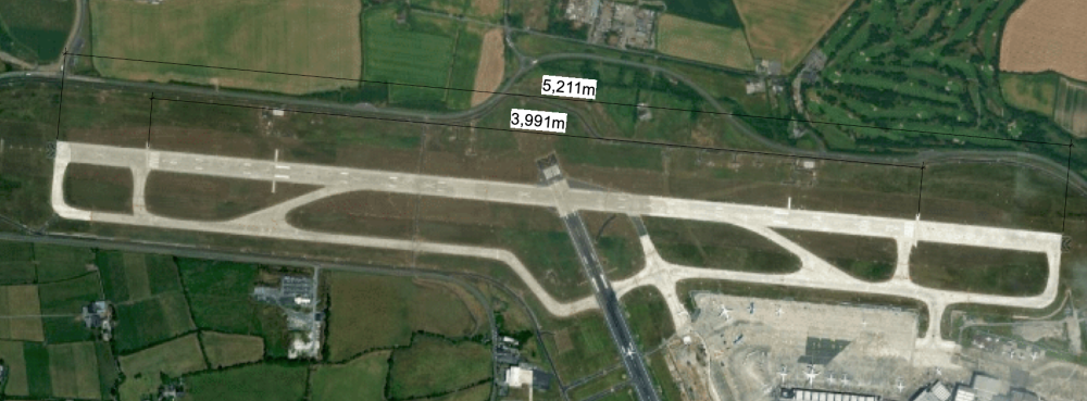
I'm not sure exactly how runway length is measured. In the cases of Dublin Airport's new north runway the length should measure 3110m. What gives?
-
The test file opened completely blank & clean.
Have you tried restarting VW?
-
1
-
-
Not sure, but you could select everything on that Design Layer, move it to a new DL and delete the offender.
-
I'm seeing persistent scaling errors of 1.5 on Geoimages of Ireland. Am I holding it wrong?
-
Several options. Roof faces are where you want to get to in the end but for preliminary study SubD works well.
1) You should start with a square- iteration 0, add an edge, drag to suit.
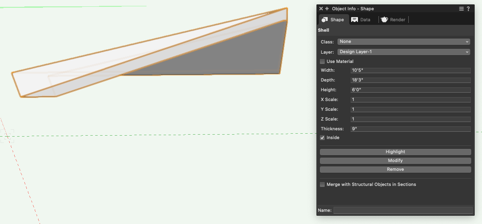
You can Modify>Convert to Generic Solids and Shell to give it thickness.
As said, (3) Roof Faces also a good option but you would need to identify the slope of the second Face to be sure it hits the ridge beam.
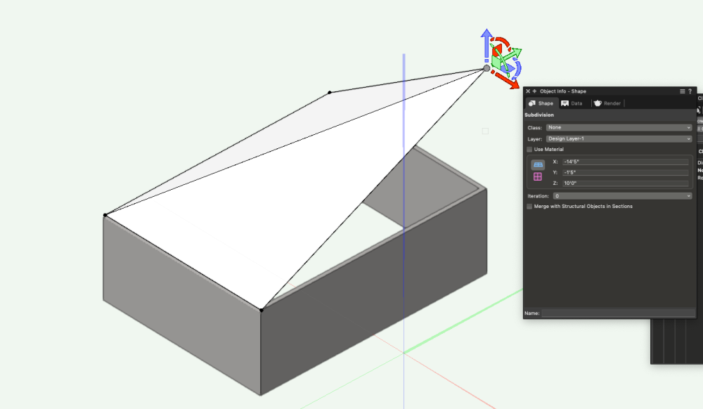
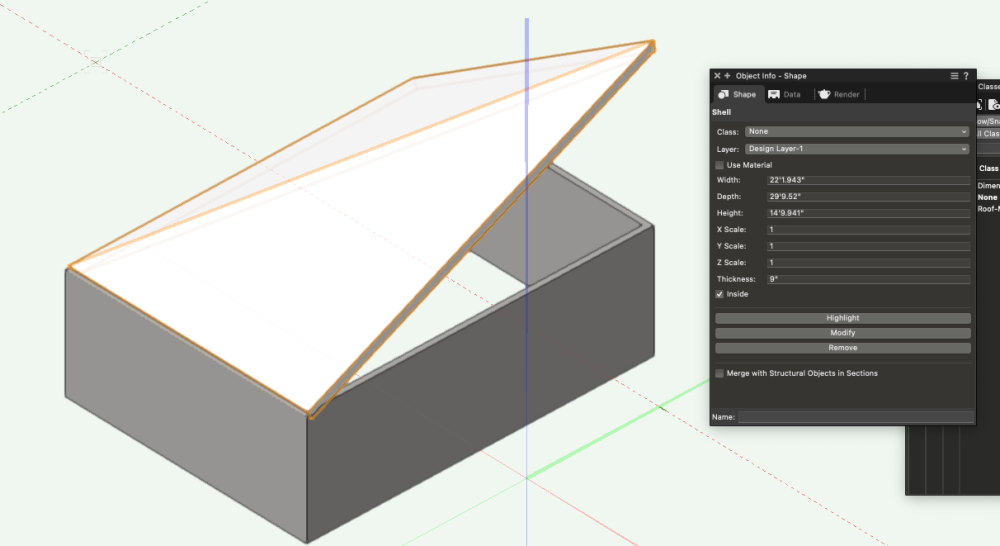
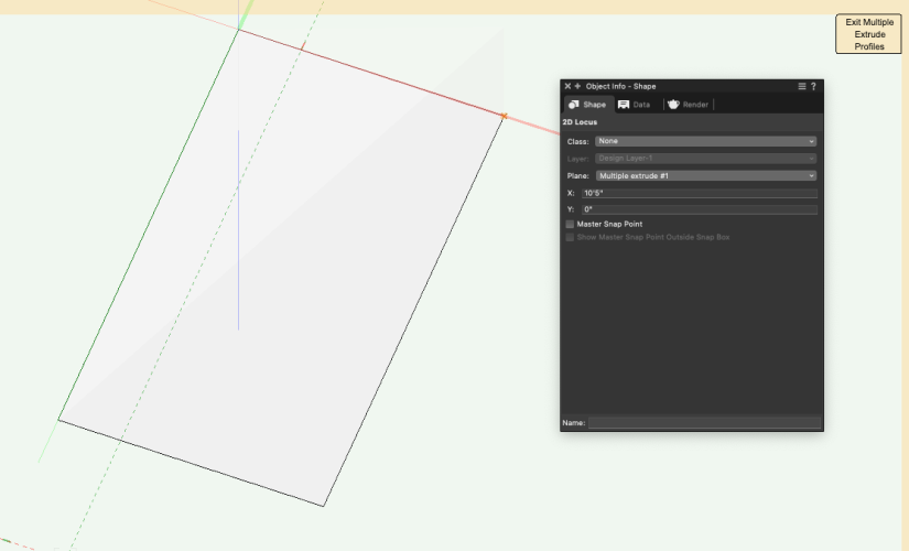
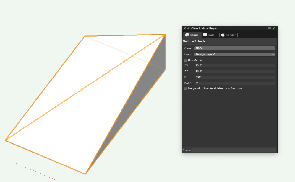
And (2) Multiple extrude is super nifty
Again shell to create roof thickness
-
2
-
-
Proof of life of the Coffee Roaster?
-
Create a Record Format, Attach it to the Symbol definition in the RM by editing the 2d definition with nothing selected drag & drop the RF.
This RF can contain all your preset Data
For clarity you can create a second RF where the dynamic data will go.
Every time you place a new symbol it will bring these two RFs with it.
You can fill the dynamic data manually on the drawing or in some cases - like numbering - via linking the RF field to the Data Tag auto-number feature.
-
1
-
-
Now, this is very typical - inserting elements into sloped ceilings & roof and VW doesn't (yet) have this figured out. It's definitely something that needs to be addressed, As well as the option to auto-scale the 2d component in one direction based on the roof slope.
The easiest solution now is do delete the 2d component and rotate it in a side view.
However, there is an awkward workaround: if it's a rectangular object and you model the sloped ceiling as a Roof Face.
Model it rotated 90º to the x-axis and convert it to a 3d Symbol.
Make sure it's set to auto-assign it to the Roof-Skylight class.
Now when you place it VW will think it's placing a skylight in the roof face.- but you'll still need to edit it on the ceiling (roof) as the left hand still thinks it's a dormer window.
-
Thanks Pat, that's good to know.
-
1 hour ago, David S said:
strangely satisfying 👍
-
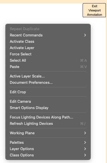
Editing Viewport Annotations>Contextual menu - Edit Design Layer is missing in VW2024
-
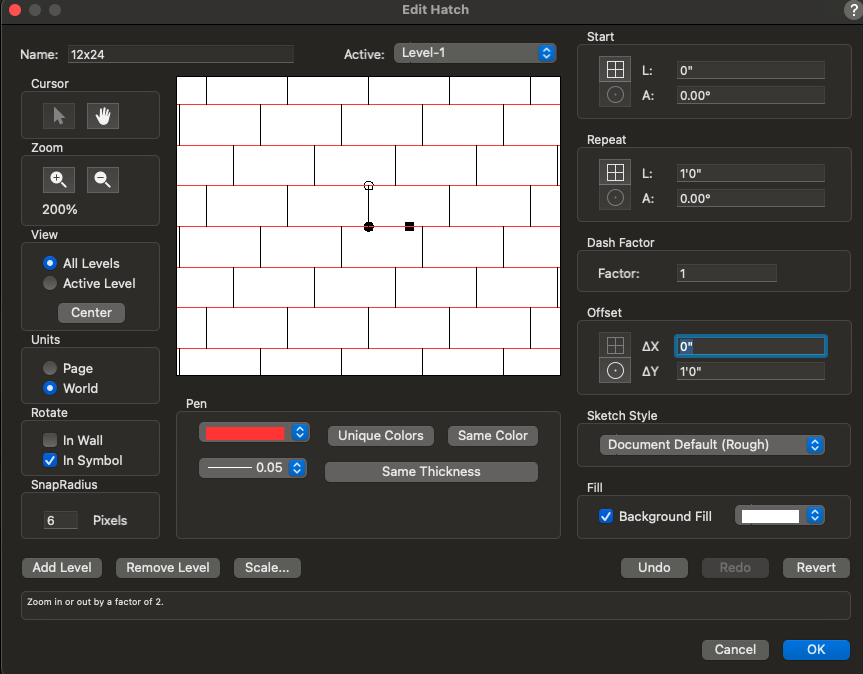
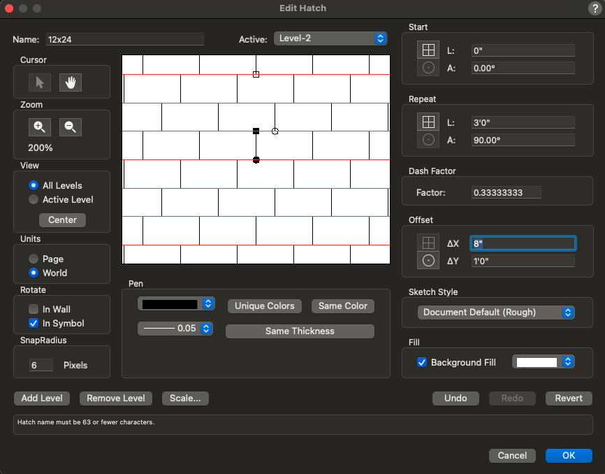
Yes! And I used 1/3 btw instead of 0.3333... to keep it as precise as possible.
-
2
-
-
2 Levels are all you need. I rotated it 90º here to match your reference.
-
2
-
-
=L in B1 will show you which Layer they are on.
-
Also use Layer as a criterion in the Custom Selection
This way you will be able to see the number on the selected Layer,
Cycling through a few likely candidates will quickly show you where they are.
-
I'd like to be able to drag & copy multiple fields at once and use this for operations.
eg. select across the x&y fields here, Copy
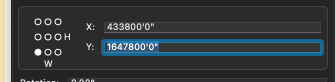 and Paste into the Move, Set User Origin, command etc. with/without a minus.
-
3
-
-
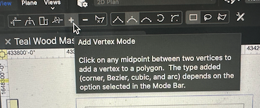
The information for the Add Vertex Mode isn't accurate.
You need to click>drag>click to add a new vertex.
However, I'd prefer if you could simply click once anywhere along the Polyline to add a point right there. Much like you can use the Split tool in Point Split mode.
-
2
-
-
This @bugsubmit is still happening.
A Group of DLVPs will become selected if the marquee touches them.
-
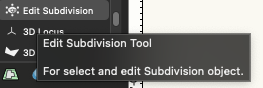
I see the text says 'Edit Subdivision' even though one click to edit, double click to create.
Not the most elegant
&
'For select???' - that's odd phrasing
-
1
-
-
5 hours ago, LuukW said:
Is there perhaps another way to reduces vertices?
Try using the Polyline tool to draw over the drawing. You might do it in increasingly complex shapes so you get off to a good start.


Missing "Add Dimension(s)" contextual menu item in VW2024
in General Discussion
Posted
In the Design Suite workspace?
Maybe a restart is required.