


C. Andrew Dunning
-
Posts
1,158 -
Joined
Content Type
Profiles
Forums
Events
Articles
Marionette
Store
Posts posted by C. Andrew Dunning
-
-
-
Mark -
The "LYON-W" Symbol (the one NOT including the pull-back - in the file you sent) contains both Generic Solids and the embedded "Rigging Frames" Symbol. It is that Symbol that is causing issues.
As to "non-Hybrid," the tools should throw errors w. that...
-
Mark -
I found the issue in the file you sent: The Symbol contained an embedded Symbol (the rigging frame) and AutoHyrid was failing at that. I converted the embedded Symbol to a group (Cmd-K) and all worked beautifully. Now...rendering/regen time w. something that detailed is another story, entirely...
-
The Autohybrud system might not be sure what to do w. some elements. Shoot me a copy of the file and I'll take a look.
-
DEselect all geometry.
See the latter pages of the ATS manual for more detailed info on the data Symbols need and the correct formatting.-
 1
1
-
-
Mark -
At-present, the tools only recognize the 3 speaker types and a single bumper type. That being said, you CAN trick the tools by creating a speaker Symbol (w. all data attached) that is actually the pull-back bar. That Symbol would then become one of the 3 types in your array.
-
1
-
-
Your signature says "VW 2019." Would you confirm that that is incorrect? (The stock Spotlight audio tools earlier than 2021 don't support Symbols...)
-
@Mike Ross, see the attached file. Is this what you're wanting to do? If so, look at how the 2 projectors are formatted - in terms of both the geometry location relative to the Insertion Point and the dimensions entered in the attached Record.
-
4 hours ago, Mark Aceto said:
The Draw 3D Only checkbox for the truss symbols would be my dream scenario for LED video screens too (adding the ability to insert 3D symbols of tiles and bumpers
Noted. 😉
-
1
-
-
43 minutes ago, Mark Aceto said:
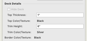
And you know how I love to use the Landru / stock tools to work around missing functionality. On that note, is there a way to adjust the width of the "trim" of stage plug objects to match the profile of stage deck objects?
At-present, no. The trim width is hard-coded.
-
6 minutes ago, Mark Aceto said:
Speaking of trim height, I can't believe I never noticed this before (sorry, I couldn't resist):
Insert snide comment. 😉
-
 1
1
-
-
9 minutes ago, Mark Aceto said:
@C. Andrew Dunning I'm all good with truss and lights (and 3D objects that aren't hybrid). It only seems to be an issue with stage objects (which I guess I've never tried before) or other hybrid objects that aren't lights.
You can add those things to DLVPs already raked but you are correct in that you can't adjust rake for DLVPs containing those objects. This is not new.
-
51 minutes ago, markdd said:
I'm afraid that function does not work any more...... more's the pity....
You might want to double-check that. I just created a quick raked DLVP. Works as-expected.
Now...what does NOT work is fixtures' auto-focusing from within DLVPs.
-
1
-
-
3 minutes ago, Mark Aceto said:
I tried rotating a DLVP with stage objects but I get the ole "hybrid objects can only be rotated... " error message. Maybe I'm missing something?
You have to have at least one Lighting Device in the "source" Design Layer. Insert a "Dummy" fixture and hide it.
-
20 hours ago, Mark Aceto said:
Does Plot & Model view still exist somewhere? I can't find it in the workspace editor...
Whether P&M exists or not, you can accomplish the same thing (w. a lot more control) using Design Layer ViewPorts.
-
@jayden.s, at-present, your best option is, as you're thinking, to illustrate resolution changes using the content you map.
-
...so..."Flip" IS what you want but (st-present) speakers can only be tilted +/- 90° and, to do that face, you'd need ~126°. It looks like you'll need to create a "B" version of that Symbol - one w. the un-rotated/un-flipped orientation rotated -90 while in Top/Plan.
-
Send me a file containing the Symbol and some sort of indication of which face you want to be "bottom..."
-
Did you try the "Flip Orientation" toggle? That and "Actual Tilt Angle" might give you what you're wanting...
-
Posting this in multiple places as I'm getting repeated inquiries regarding this...
Many users are having issues with certain bumper and speaker Symbols when used with our Audio ToolSet 2 tools and the stock Vectorworks® audio tools - mainly, when building arrays. They're seeing things like arrays with HUGE spacing in-between elements, guide-lines being WAY longer than the bumpers and speakers of which they are part, and Symbols in the Array Config dialog preview boxes displaying at a fraction of the desired size. (Sound familiar??)
The problem is that in very early versions of the "__ATS-BumpModData" and "__ATS-SpkrModData" records the different dimension fields ("Front Width," "Depth," "Thick," etc.) were defined as "Number" fields defined as Dimensions. This was all well-and-good as long as "Imperial" Symbols were never used in "Metric" models and vice-versa. When this happened, Vectorworks® got confused and did things like thinking 520mm is 520'. This was fixed several years ago but some of the content in Vectorworks'® catalog has not been updated, yet.
So...if you're seeing this sort of thing...while the file containing the Symbols you wish to use is open...:
1) In the Resource Manager, right-click on either the "__ATS-BumpModData" record or the "__ATS-SpkrModData" record and select "Edit..." In the dialog that opens, all of the entries in the "Type" column should be "Text." One-by-one, select the entries that are not and click the "Edit..." button. In the "Type" Pop-Up, select "Text." Click "OK," fix the next one, and so-on. When finished, click "OK" to close the "Edit Record Format" dialog.
2) Still in the Resource Manager, right-click on the problem-child Symbol and choose either "Edit 2D Components" or "Edit 3D Component." With NOTHING selected (click in open space), click on the "Data" tab of the Object Information Palette. Either "__ATS-BumpModData" or "__ATS-SpkrModData" will be in the "Record Format" window. Select the given record and check and/or correct the dimension values that will be in the lower part of the OIP. MAKE SURE EACH VALUE INCLUDES THE APPROPRIATE UNIT MARKER (',",mm,m, etc.). As mentioned above, you might find things like 520' that should be 520mm. When all is correct, click the "Exit Symbol" button in the drawing space.
Save your file. All should be good - though you might have to click the OIP "Update" button for the different object instances in order for the changes to take effect.
I hope this helps some of you...
-
2
-
-
Have you looked into either the Spotlight Soft Goods tool or our SoftGoods 2 tool?
-
8 hours ago, Mark Aceto said:
Is there some functionality built into selecting hoists in the OIP?
I was expecting to select hoist symbols next but it doesn't seem to go anywhere after choosing the hanging support...
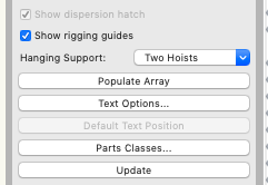
No. This is just for data tracking & display.
-
2
-
-
2 comments / bits of info:
1) The record attached to the bumper in the demo file was an old version, one in which the different dimensions were held in "number" fields. When switching back-and-forth between Metric and Imperial (or, using Symbols created using the other unit convention), VW got confused and tried calling Metric dimensions "Imperial." The new Record format changed those fields to "Text" to fix this sort of issue.
2) When using these fields, the units marker must be included so VW knows what the number means when translating it from text. The dimensions can use whatever length units are desired - as long as the unit marker is included. This will allow, for example, "Metric" Symbols to be used in "Imperial" files.
See attached. Same bumper in each array, one defined using Metric dimensions and the other, Imperial.
-
1
-
-
A regular question...which I received again yesterday...is along the lines of "With the release of the new VW version, what is different in the Landru Design version of the tools?" I'd offer 4 things, 1 regarding all of the tools and 3 regarding specific tools:
1) All of the tools work in all versions of VW, 2018>2021 - whether you own Spotlight, Designer, or Fundamentals. This means that, as long as everyone on your team has current licenses for our tools, instances of our objects work equally well, regardless of everyone having the same VW version.
2) All of the video tools offer 3D Text blocks, meaning you can display select data (like LED array size and make-up) superimposed over the array's image.
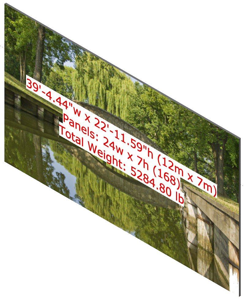
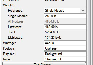
3) VS4-LED includes on-the-fly weight estimating, allowing you to input a single panel's weight and get an estimate of an array's overall and distributed weight.
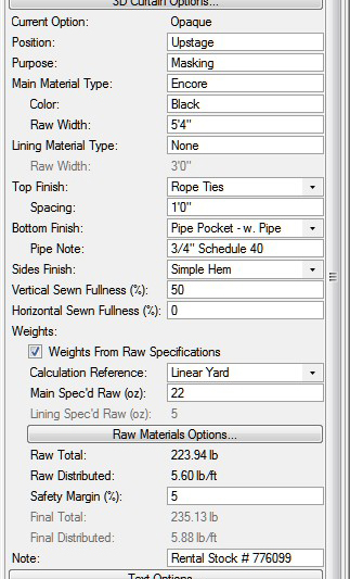
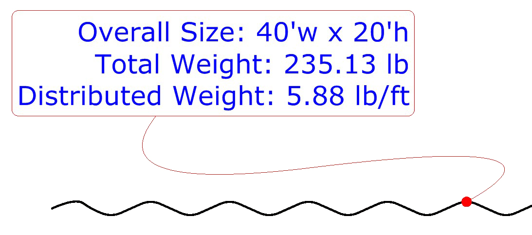
4) SoftGoods 2 has a "Weights From Raw Specifications" mode that allows you to enter spec. for fabric, pipe, chain, track rollers, etc. and be given an estimate of the curtain's an array's overall and distributed weight - both of which change as you re-size the object. Also, SoftGoods 2 has the same "Text Bubble" feature that some of you have seen in the audio tools.
I hope this helps those of you who are asking...
-
1
-


Speaker Array - Rigging Frames & Pull-Back Bar
in Entertainment
Posted
100% my pleasure!