


C. Andrew Dunning
-
Posts
1,153 -
Joined
Content Type
Profiles
Forums
Events
Articles
Marionette
Store
Posts posted by C. Andrew Dunning
-
-
100% my pleasure!
-
Change the default character for "Universe/Address" on the "Lighting Devices/Parameters" tab in the Spotlight Preferences dialog.
-
3 hours ago, STA said:
our company has some custom made speaker stands, which we would love to use with the speaker tool.
Is there a way to incorporate them, so I can choose them from the dropdown?
At-present, no, The tool only uses the stands it creates on-the-fly.
-
We are happy to announce that all of our tools have been updated to make them Vectorworks 2022®-compatible!
In addition to the usual on-going refinement, you might also notice minor additions and tweaks like "Vendor" and "Cost" fields, hardware Texture control for SoftGoods 2, and 3D Text Blocks for the Staging ToolSet tools.
All of the tools will work in any "flavor" of Vectorworks 2018-2022.
If you're a current user, you should have received upgrade details in the last few days. If you'd like more info, please visit https://www.landrudesign.com/VWPlugIns.htm
Happy Vectorworking!
-
 4
4
-
-
Is the issue w. the Spotlight version or the Landru Design version?
-
1
-
-
...and...while the content is a few years old, this video outlining building your own custom projectors, TVs, and stands is still relevant and might be helpful:
-
You can copy the Symbol into yiur current file. If the Symbol has the correct Record attached (and, the data is correct) the PIO will recognize and use it.
-
1
-
-
On 8/6/2021 at 7:49 AM, Ben59 said:
hello thanks for answer !
Are talking about "classes part" at the bottom of the OIP and int the configuration tool ?
if so, it only works for part of the plugins...It will be nice if that menu's option will be in the configaration menu and by the way OIP
Yes, that is what I meant.
Sorry, the functionality you're wanting isn't part of the mix at this time...
-
Have you tried using the "Classes..." button at the bottom of the OIP? You can assign some or all of the parts to Classes using that dialog.
-
The hatch creation system hasn't changed in several versions. Is there any way you can post a demo file showing this problem so we can figure out whether there is something awry in the tools or in the file?
-
Antoine -
If you look at the "__ATS-SpkrModData" or "__ATS-SpkrModData" Record you'll likely find that the different dimension fields (Width, Depth, Thick, etc.) are using the incorrect units. First, make sure that they are TEXT fields (NOT Dimension). Second, make sure that the values they contain include appropriate units markers (mm, cm, ", etc.). If you check and fix those fields and values and then open and close the Config dialog, things should right themselves.
I hope this helps.
-
You likely have something in your file named "5" - could be just about anything. If you can identify and rename that item, you should be able to use "5" as a Focus Point name. In your case, it was a Working Plane.
I've attached a file containing a Script that can help you fix such things down-the-road.
-
I believe so...
-
3 minutes ago, michaelk said:
Is it possible to define a control point in a plug in but not have the handle visible until it is needed?
Yes. Use SetCntrlPtVis (something along the lines of "SetCntrlPtVis(ghParm,1,FALSE)").
-
Are you running VW 2021? Is your Workspace from a previous version? If so, use the Workspace Editor to remove the tool that is there now and add the new one that shows up in the left-hand pane.
-
1
-
-
1 hour ago, trashcan said:
For both of you - is there a way to simulate focus tolerances vs. viewing distance?
Focus tolerances, no. Optimal viewing area/zone, yes.
1 hour ago, trashcan said:wondering if there's been an update to your tool to allow for Vertical blends as well as Horizontal.
At-present, still only horizontal blends. Sorry...
1 hour ago, trashcan said:I am also wondering if VS4 allows for variable projector positioning? Also curious if there are some updated tutorials for the tool (that show you the curved video wall feature, for example)?
Yes, projectors for a given "blend family" can be independently-positioned.
1 hour ago, trashcan said:Also curious if there are some updated tutorials for the tool (that show you the curved video wall feature, for example)?
While our documentation has been updated recently, I'm not sure that you would call it a "tutorial." And, admittedly, it has been a while since I've done one of those.
-
1
-
-
On 10/15/2020 at 6:12 PM, A.D.K. said:
My main ask: side hangable projectors. I need my calcs to be for 10:16, not 16:10! I can't see how to do this, and it's a thing we do a lot.
Sorry; just seeing this thread...
If the projector Symbol name includes the text "-Side" the tools know that that projector has a portrait orientation. The projector aspect parameter is then enabled, allowing you to spec. that.
-
3
-
-
Have you tried the built-in Batch Rename command?
-
4 hours ago, Mark Aceto said:
I like the "+30" because that's the only text field I'll add vs Dimensioning. That said, I only use it in Plan view.
I would think ramps and steps don't need labeling in 3D because the slope indicates direction up/down, and the heights at top/bottom are already labeled, so it would just create visual clutter.
Look at all of the potential text items that could be displayed - beyond arrows and their labels. While I, personally, might not use them in 3D, I can definitely see others' valuing that.
-
For anyone following this thread...
Adding a setting to echo the 2D text block in 3D within the PIO, itself, is quite doable. For decks and plugs, the text block would simply "follow" the 2D location but would be at the "deck top" height: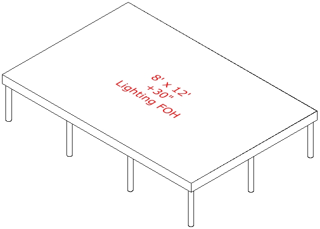
My question: if this capability were to be included for the steps and ramp tool, would you want the text block to be at the height of the top step or ramp top? At floor level? Aligned (raked) with the angle of the steps or ramp? Something else?
-
1
-
-
8 hours ago, Matt Strong said:
I'd love to use the Video Screen tool to drop in our proj/screens, but the roll-down screen only has one header height, and I can't customize the screen box to be higher up with a taller header above the screen. Is this possible another way?
You can change the "header" height by entering different values in the "Top" "Border Width" box.
Does that help?
-
1
-
-
On 6/11/2021 at 6:58 PM, djobbins said:
This has been since at least v2020.
This does sound like pretty odd behavior for the pre-Symbol version. If you'd like to DM me a sample file, I'd be happy to add it to my "take a look" list.
-
Regarding bogging down...: Are you using "Symbol" mode for either bumper or speakers? If so, are your Symbols fairly detailed...what is the rendering mode for the Config dialog preview boxes...and, are the the bumper and any of the speakers tilted? If so, try less detailed Symbols or Catalog/Library mode. Highly-detailed Symbols take longer to render. in the Config dialog. And, tilting elements in Symbol mode involves creating AutoHybrid geometry for each instance in your model, which can be time-consuming.
Regarding the dialog going beyond your screen limits...: Check your computer spec. against recommended minimums. With the last version, we actually worked on reducing the size of that dialog so as to work better with computers with the minimum specs.
-
On 5/18/2021 at 8:43 AM, markdd said:
Data Tags will be the way to go....
And...or...reach out to the developer about a possible feature tweak... 😉
-
4
-
Survey regarding the current Spotlight LIR [Light Info Record]
in Wishlist - Feature and Content Requests
Posted
A "No" for me. While the attributes you cite ARE important, I don't consider them within the VW environment.
Qualities like beam/field angle and output ARE things I need within VW...