


C. Andrew Dunning
-
Posts
1,179 -
Joined
Content Type
Profiles
Forums
Events
Articles
Marionette
Store
Posts posted by C. Andrew Dunning
-
-
3 hours ago, spettitt said:
- This only works when double-clicking the red symbol in the RM (for us, in a Workgroup library folder), but not when navigating to the very same symbol after launching the Lighting Device tool.
Correct. In my workflow, I never use the Lighting Device tool. All fixture placement is via the Resource Manager. That way, Red Symbols work and I choose the specific source folder. (No issues w. a "flattened" structure like you mentioned.)
3 hours ago, spettitt said:- (Not critical, but still annoying) - The first click now works at the correct insertion point, but the rotation vector for the second click is 90 degrees to the usual vector for a hung fixture - instead of aligned with the lens, it's off to the side. Not a gig-stopper, but frustrating when switching between laying out flown and floor fixtures.
I've not seen that. Are the instances from which you built the Red Symbols using default orientation?
-
3 hours ago, spettitt said:
Therefore, to edit the actual geometry of the displayed symbol, I need to edit the orginal symbol definition wrapped inside of it, rather than the red symbol, which just has the nested symbol inside. Is that right?
Correct. Though, once-placed, you're back to a Symbol wrapped within the Lighting Device container.
3 hours ago, spettitt said:The only issue is that when inserting the red symbol, it doesn't use the insertion point of the fixture, but rather a point out on the movement radius, which is frustrating when trying to lay fixtures out.
2 things:
Within the Symbol Creation dialog, make sure "Plug-in origin" is selected under "Insertion Point:"
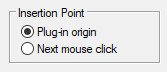
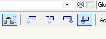
When inserting Lighting Device Symbols, make sure the last mode is selected:
-
 1
1
-
-
4 hours ago, spettitt said:
I would be interested to know how people place moving lights on the floor - i.e. base down, lens up. I seem to have a choice between having them correct in Top/Plan or correct in MVR output.
1) Create all Lighting Device Symbols using the default of lens-down/bottom hung. Let Vectorworks control the 3D orientation using the Rotation fields at the top of the OIP. Use "Custom plan rotation" (toward the bottom of the OIP) to correct any 2D issues. (Y = 180 - which VW will change to X = 180/Y = 0/Z = 180) will cause floor/top-hung orientation). This will make things work w. Vision/MVR.
2) Create separate Symbols for each of your desired orientations - 3D following the above convention and 2D being different for each orientation. This will make your intent more obvious on your plots.
3) After your initial Symbols are created, place an instance of each, making orientation/rotation changes as-desired. Attach Label Legends and enter any default data (like mode).
4) Create Red Symbols of these instances.
5) When designing, instead of placing Black Symbols, place your new Red Symbols. This way, orientions will be pre-set, data will be pre-attached, and Label Legends will be pre-configured.See attached for a simple example.
-
2
-
-
20 hours ago, Gary Seputis said:
I'm not seeing the file - is it still available?
Sorry, no...
-
2 hours ago, LarryO said:
I am trying to think how a plugin could call up a texture if the texture/image was not already present in a drawing file. Would the image have to be in the plugin folder?
The bulk of the Spotlight/entertainment/production PIOs apply code-generated (non-image) Textures.
So...2 things:
1) The tools first check to see if the given Texture exists in the local/working file and then create it if it doesn't. This lets users tweak/edit Textures (once created) if they wish.
2) The different Texture settings can be challenging to fugure out. The easiest way to get those settings is to create the given Texture and to use "Export Vectorscript."
-
1
-
-
On 2/24/2022 at 1:55 PM, Josh Schulman said:
NYC and other locations are changing their stair requirements for temporary events. Currently there is no way, without ungrouping and breaking the plug-in) to add additional horizontal bars to a Self-Adjusting set of stairs using the Stage Steps Tool.
...
The Railing prefs are greyed out. Could this be changed or is it best practice to continue to ungroup stairs and break the plug-in?
The Landru Design version of the tool now has this feature:
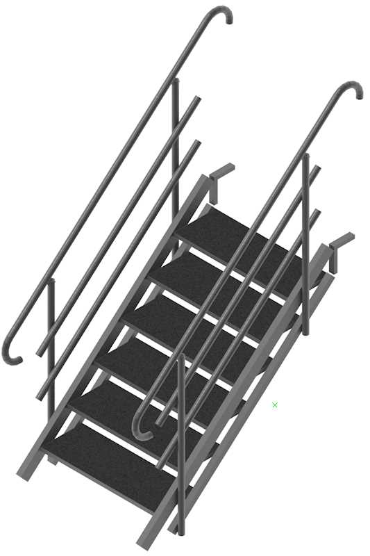
See our Plug-Ins page for more info.
-
3
-
-
5 hours ago, Pier180 said:
No issues, here. I opened the file, selected the Speaker Array instance, clicked the "Configure Array..." button, switched to the last pane and changed speaker angles, and clicked "OK." The array re-built itself just-fine.
I did see that the dimension fields in the Record attached to the bumper need units markers but, as your file is in mm (the same unit used by your bumper), you shouldn't have any problems.
-
11 hours ago, Pier180 said:
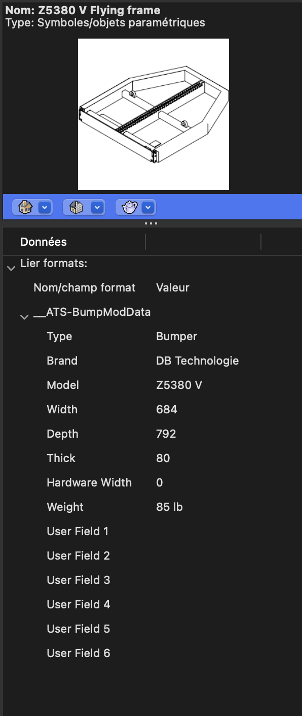
Be sure to include units markers ("mm") in the dimension fields of this record. Otherwise, if this Symbol is ever used in a file with anything other than mm as it main linear dimension, you'll have placement and spacing issues.
-
20 hours ago, Pier180 said:
I import a symbol source and it displays it well in the speaker array tools but when I insert the speakers in the drawing I have a simple geometry speaker ?
I don't understand where is the option?
When in "Catalog" mode (or, "Library" in the Landru Design version), "Import" will import the data from the Symbol but will build the simplified model on-the-fly. When in "Symbol" mode, the tools will use the actual Symbol geometry. If your given Symbol has the same name as a Catalog/Library entry, you can switch back-and-forth, essentially giving you an "intricate" and "simple" mode.
-
On 3/29/2022 at 1:57 PM, Mark Aceto said:
what do you think about Custom plan rotation for PJ's? That would help when using 3 diff lenses that are all slightly different (and 2D lens style / text would clarify that on the plot).
FINALLY have a minute to work on The List. Just added this...
-
 1
1
-
-
14 hours ago, Pat Stanford said:
Thank you Andrew. I just wanted to make sure it was not something I was not understanding.
No problem.
FWIW, the problem I'm seeing w. the Landru Design version is new to 2022.
The problem: Image is flipped horizontally and starts from the wrong end of the curve.
Open this file in 2021...
-
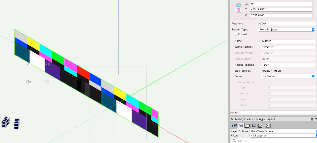
6 hours ago, Pat Stanford said:
Only because I'm curious, but it still does not seem to work properly for me.
This is without Curved selected for the screen

and this is with the curved screen.
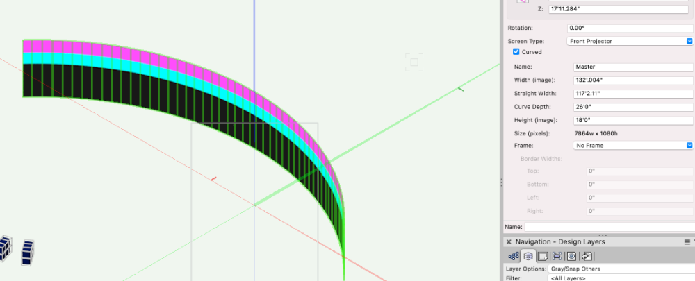
The only change I made was to set the screen curved. Shouldn't the image be the same in both cases?
Here is a file containing instances of the Spotlight PIO and the Landru Design version. While the faceting issue is gone w. the Landru Design version, clearly, I need to delve back into this tool a bit...
-
9 minutes ago, Andy Broomell said:
One workaround I found is to click the Classes button in the OIP, put the Frames on a class, then turn that class off. This leaves just the textured screen without the black frame, eliminating the stripes popping through.
Choose the "No Frames" Frame option.
-
Editing my response...
I see the issue in every rendering mode w. the Spotlight version of the tool. I then inserted an instance (w. matching settings) of the Landru Design version. Zero issues. Likely something that got tweaked along the way that has not made it into the Spotlight version, yet.
-
56 minutes ago, Ben59 said:
Is a way to customsize the size of the television in the television plugin ?
You'll need to create a Symbol for the television you're wanting to show. Toward the end of the manual found here: https://www.landrudesign.com/VWPlugIns.htm are instructions as to how to do this. We also have a movie showing this here:
The movie is pretty old and the tool has undergone a little evolution but the core ideas are the same.
-
1
-
-
59 minutes ago, Mark Aceto said:
- Use the data record and data vis for black truss. There's no need to have a different symbol for a different color (although that's fine too).
Different Symbol = different color and texture applied to 3D portion....and, embedded text label noting color w/o needing to make record changes.
-
1 hour ago, Mark Aceto said:
I guess what you’re saying is to select similar and then let the tool do the work?
Couldn't have said it better, myself... 😉
-
1
-
-
28 minutes ago, Mark Aceto said:
I bet you even have a fancy script to execute this in one sweep...
Not a fancy extra script but hard-coded into the tools...
-
1
-
-
If you don't mind poking around Vectorscript a little you might find the Worksheet and Script in the attached file to be helpful. While the dimensions get reformatted to the closest .XX", that would be easy enough to adjust.
-
...and...if the Symbol name and Catalog/Library name are the same the tools will automatically grab the right "other" when you switch modes.
-
1
-
1
-
-
15 minutes ago, Projx_CA said:
The Audio Array tool in Spotlight is very useful, but also very difficult to work with on complex arrays.
Processing time on the CPU for a single array with 3 types of boxes can take 10 minutes or more, with the entire program being unusable during that period.
GPU is not enabled for this, even if modified in Shaded mode.
You're running in Symbol mode, correct? If so, something that might help is to switch to Library/Catalog mode when initially building and placing arrays. Then, switch to Symbol mode for final drawings. That will at least help you to work quicker until you need more detailed models. Another option that may or may not be acceptable is to use less detailed Symbols.
-
1
-
2
-
-
1 minute ago, Mark Aceto said:
Very much looking forward to autohybrid PJ's in Landru / stock tools! I know it's on the list 😅
It is... 😉
-
1
-
-
5 minutes ago, Mark Aceto said:
The light plot analogy only applies to lights.
I'd argue that there is a good bit (at a certain level) of similarity. For both, the Hybrid system is good for simple hangs (think horizontal truss with bottom-hung fixtures). Things break down quickly when steering away from that - which is why things like raking Design Layer ViewPorts and Schematic Views have been pursued. Designers in both disciplines need to communicate details clearly - especially, when "non-conventional" approaches are desired. Judging from threads over the years (including this one), we're still in search of a good solution...
-
On 3/12/2022 at 10:56 AM, fuberator said:
So, does the 2D symbol part of a projector hold so much value that it can't just be fired? Or optionally disabled in the OIP?
Sorry for the delay in replying. Lots of juggling these days...
Interesting food-for-thought.
To answer your first question, I'll draw a parallel w. Light Plots. There is a big difference between 2D icons shown on plots and 3D models. The latter would make for illegible plots. While, perhaps, not to the same extent, I'd offer similar thinking w. projectors, screens, and other video elements.
As to your 2nd question, definitely something worth giving consideration.

Video screens
in General Discussion
Posted
Like Pat said...
If you don't have Designer or Spotlight, you have the option of buying our versions. In some cases, the tools are essentially identical. In others, the Landru Design versions have expanded functionality.
Feel free to reach out if you'd like more details.