


C. Andrew Dunning
-
Posts
1,155 -
Joined
Content Type
Profiles
Forums
Events
Articles
Marionette
Store
Posts posted by C. Andrew Dunning
-
-
Does anyone have any other recommendations?
I know you only asked for mouse feedback, but...
I'm not at all a mouse fan. I MUCH prefer trackballs and have been using - and, really liking - Logitech's Trackman II for several years.
-
Steven -
You might want to give Wood Workshop a try (http://www.spiralgraphics.biz/ww_overview.htm). It is a generator for seamless wood textures.
-
Sam -
Echoing what Matt said, there is a REALLY good chance that you don't have problematic scripts or a corrupted WorkSpace - but an over-populated WorkSpace. I've paid the tax on that one several times, chasing what I thought to be bugs in code (and, annoying other developers about their "broken" scripts), only to find that I had passed some sort of undocumented limit in menu items. More often than not, doing some menu "weeding" fixed things. Your mentioning some sort of correlation between command position in the WorkSpace and the command working is the big indicator along these lines.
-
Once the report is made, is it possible to go back and edit / reorganize the chosen fields?
All you have to do is to make the header row visible ([View][Database Headers]) and click in the header cell over the column you're wanting to change. You'll see something like "=VALUE(('SoftGoods 2'.'TTLSGLngth'))." The text in the second set of single quotes is the name of the parameter field you're reporting. Change that text to match the name of the field you're wanting to display. If you're not wanting to display actual numbers on which you're wanting to perform functions, remove "=VALUE(" and one of the trailing ")s." For example: "=('SoftGoods 2'.'Color')"
Does that help, at all?
-
Bryce -
Give [File][Export][image File...] a try.
-
Ethan -
Assuming you're in the Spotlight WorkSpace...
[spotlight][Reports][Create Report...]
- Give your report an appropriate title.
- List all: Objects with a record
- Listing objects with record: SoftGoods 2
- From the left-hand List Browser, select the fields you want in your report and click the "Add >>" button.
- Click "OK."
A Report will be generated.
[View][Database Headers] will show or hide the database header row. Right-clicking on the row number for that row will give you the ability to "Edit Criteria" further.
Adding "=Value" to numeric column headers will let you perform mathematic functions (like, adding up drape counts) on columns.
I've attached a simple file showing some of this being used to get Pipe-and-Drape counts for SoftGoods 2 instances.
I hope this helps...at least a little...
-
Frederick -
Your best bet is to create a Video Screen instance (configured the way you want it) on a separate Design Layer and then to insert a Design Layer ViewPort (DLVP) referencing that Design Layer. Then, tilt/rotate the DLVP to the orientation you're needing. Any adjustments you then make to the actual PIO instance will be reflected in the DLVP.
Does that help, at all?
-
Chris -
I see you asked the same question over on Lightnetork and am posting my expanded answer from there here in case others are following this thread.
3 options come to-mind:
1) Duplicate and rotate: Duplicate 1 or more VS4-LED/LED Screen objects in-place and use the rotate tool to rotate the duplicates around a known radius, using points 1, 2, and 3 in the attached graphic.
2) Duplicate Array: Get angle A in the attached graphic (probably, by placing a temporary arc - the green object in the graphic) and run the Duplicate Array... command, using the "Circular Array" Shape, entering "17" for the "Number of Duplicates," and angle "A" for the "Angle Between Duplicates" - making sure you toggle "Rotate Duplicates" on and use the shown circle's center as the rotation center (Next Mouse Click").
3) Polygon (probably only used if you're needing to make a complete circle of LED panels): Place a Regular Polygon and use "Reshaper" to calculate the number of facets that (In your case, 114 facets would give you a 9.073m circle or 113 facets would give you a 8.99m circle). Then, place a VS4-LED/LED Screen object on each facet.
-
Larry -
Your 2nd question first: You access Plug-In Strings using the "GetPlugInString" call, as in "GetPlugInString(5001)" to grab the string stored in location 5001.
Now, your first question: They're used anywhere text strings might be used, allowing for relatively easy language localization (as opposed to having to write specific code for different spoken languages). Examples:
- Any and all dialog labels and helps.
- Dialog pop-up contents (like "Top," "Bottom," and "Center").
- Error messages.
- Labels for displayed text (such as "Type" in the Speaker tool).
- Class names specific to and created by a given PIO.
- Names for Resource a given PIO might generate (like the black deck texture in the staging tools or the Coverage Zone hatch in the video tools).
- OIP button labels and separator text.
That help?
-
I'm glad things worked.
I know things seem a bit convoluted but this is one of those times in which the coding intricacy might be needed by some users - and, this call works independently of what menu items a user might have in his/her WorkSpace.
If you care to, you also have 2 other options. Look into "CreateExtrudeAlongPath" and "ExtrudeAlongPath." The latter is a newer call I haven't tried, yet, and the former actually creates 3 objects: the EAP shell and 2 end-caps.
-
Try this...:
procedure Pipe;
var
h1, h2,h3,h4,h5 : handle;
PipeOD, Wall, p1X, p1Y, p1Z, p2X, p2Y, p2Z : real;
begin
PipeOD := 42.4;
Wall := 3.2;
Message ('Pick first and last points.');
GetLine3D (p1X, p1Y, p1Z, p2X, p2Y, p2Z, false);
Poly3D (p1X, p1Y, p1Z, p2X, p2Y, p2Z);
h1 := ConvertToNurbs (LNewObj, false);
Oval (-PipeOD/2, PipeOD/2, PipeOD/2, -PipeOD/2);
h2 := LNewObj;
Oval (-PipeOD/2 + Wall, PipeOD/2 - Wall, PipeOD/2 - Wall, -PipeOD/2 + Wall);
h3 := LNewObj;
ClipSurface (h2, h3);
h4 := PrevObj(h3);
h5 := CreateCustomObject('Extrude Along Path',0,0,0);
IF SetCustomObjectProfileGroup(h5,h4) THEN BEGIN END;
IF SetCustomObjectPath(h5,h1) THEN BEGIN END;
DelObject (h2);
DelObject (h3);
ClrMessage;
end;
run (Pipe);
-
Alan -
When you created your Lighting Positions, did you create them on the Ground Plane BEFORE moving them to-trim? If you didn't, try that to see if that fixes the issue.
-
Chris -
Use the Regular Polygon tool to create an 18-side "construction" object with that radius. Then, place LED Screen objects around that polygon, aligning each LED Screen instance with the facet angle.
FWIW, I often do that and use ReShaper (http://siriussolutions.net/details%20r13.html) to edit things like facet number or width or over-all radius. An incredibly helpful command for doing things like that...
-
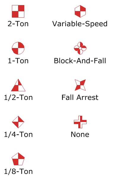
Andrew, I think from the symbols you posted the None would be the same as a dead hang.
Correct. I just chose not to use the phrase "dead hang" in my key as I didn't want that label to get confused with "bridleless."
-
Chad -
I think Benjamin is correct. As long as you note what a particular Symbol represents, you're probable good. I'd just avoid one of the other standards.
FWIW, here is the point convention I use:
[img:center]http://www.landrudesign.com/Downloads/RiggingKey.jpg[/img]
-
Is it possible to move the stacking order of the text separate from the video objects? In other words, if I have a screen and projector flown under truss, the text populates under the truss and is partially obscured.
You can't change the stacking order of the text independently of the rest of the PIO instance. What you CAN do, though (with all of the video tools - both the Landru and the Spotlight versions), is drag the text to where it's not obscured. Simply enable VW's Interactive Scaling mode (the 2nd icon from the left on the Tool Bar) when you have the Selection Tool active. Small blue Control Points will appear near all of the draggable elements. This is similar to being able to move Lighting Device Label Legend elements.
Make sense??
-
the buildresourcelist only gives you the names of these symbols if coming from an external resource.
Actually, feeding BuildResourceList a folder index of "0" will build a list of resources in just the current document. A negative index will build a list from just an external folder. A positive index will build a list based on both the current document and an external folder.
-
+1000
I've been asking for something along these lines for years.
The CADD package I used prior to VW had an "=" function. When drawing or editing and a distance was expected, pressing "=" would let you take a measurement w/o dumping you from the given drawing/editing command.
-
I have worked in Autodesk product for many years. Can you please describe how you use classes and layers? I have gone to help but would like to get real world examples.
I use the "Where"(Design Layers)/"What"(Classes) convention described in the video.
Where:
Either specific performance spaces or, if I am using Design Layer ViewPorts, hanging locations or structural elements (like a truss pod). This means that, if I'm not using DLVPs and am working in a single space, I'm working in one Design Layer.
What:
Lighting (conventional, intelligent, notes, dimensions, etc.), audio (PA, monitors, notes, etc.), video (projection, LED, confidence monitors, etc.), staging, scenic, truss, rigging, venue (walls, steel, safety perimeters, etc.), etc.
I end up with a TON of Classes but, with Saved Views, no big deal at all.
-
Scott -
While not in a PIO shell, here is some quick code that will create a red hexagon with partial opacity and add a middle line. I hope this helps in your endeavor...
PROCEDURE HexBox;
CONST
HexShortRad = 8";
OriginX = 0;
OriginY = 0;
VAR
LongRad,HalfFace : REAL;
HexHandle,LineHandle : HANDLE;
BEGIN
LongRad := HexShortRad/(Cos(Deg2Rad(30)));
HalfFace := HexShortRad*(Tan(Deg2Rad(30)));
BeginPoly;
AddPoint(OriginX+HalfFace,OriginY+HexShortRad);
AddPoint(OriginX+LongRad,OriginY);
AddPoint(OriginX+HalfFace,OriginY-HexShortRad);
AddPoint(OriginX-HalfFace,OriginY-HexShortRad);
AddPoint(OriginX-LongRad,OriginY);
AddPoint(OriginX-HalfFace,OriginY+HexShortRad);
AddPoint(OriginX+HalfFace,OriginY+HexShortRad);
EndPoly;
HexHandle := LNewObj;
SetLSN(HexHandle,1);
SetPenFore (HexHandle,0,0,0);
SetPenBack (HexHandle,0,0,0);
SetLW(HexHandle,40);
SetFPat (HexHandle,2);
SetFillFore (HexHandle,65535,0,0);
SetFillBack (HexHandle,65535,0,0);
SetOpacity(HexHandle,60);
MoveTo(OriginX-LongRad+1",0);
LineTo(OriginX+LongRad-1",0);
LineHandle := LNewObj;
SetLSN(LineHandle,1);
SetPenFore (LineHandle,0,0,0);
SetPenBack (LineHandle,0,0,0);
SetLW(LineHandle,16);
END;
RUN(HexBox);
-
I'm glad all is working, now!
Have a good one!
-
Thomas -
A few questions:
Are you having trouble with both the Landru and the Spotlight versions? 1 or the other?
If the Landru version, what is the build # at the bottom of the OIP?
Does this happen with all files or 1 in-particular? If 1 in-particular, would you post or send me a copy of the file so I can take a look?
-
Would I be able to add my geometry inside the individual LED Screen PIO's, or would they have to be outside that PIO geometry?
Justin -
You won't be able to add geometry within the existing PIO instance. At first glance, you'd have to do one of 2 things:
1) Create a script that searches the model, grabs suitable data, and places the desired text on the Working Plane adjacent to the PIO instances.
2) Create a PIO that places an LED Screen instance and the desired text. The LED Screen instance and your text would then be "internal" to that new PIO.
That help, at all?
-
Joe -
Assuming the Symbol was created using the recommended Spotlight convention (facing "up-screen" and pointed down), check the "Set 3D Orientation" box toward the bottom of the OIP and enter "180" into the "X Rotation" box.
Selecting Channel Range
in Entertainment
Posted
Not out-of-the-box, no. You'll want to look into AutoPlot Tools For Spotlight (http://www.autoplotvw.com/APSL_Desc.asp). I believe that must-have collection of scripts includes one that will do what you're needing.