Monique Freese
-
Posts
18 -
Joined
-
Last visited
Content Type
Profiles
Forums
Events
Articles
Marionette
Store
Everything posted by Monique Freese
-
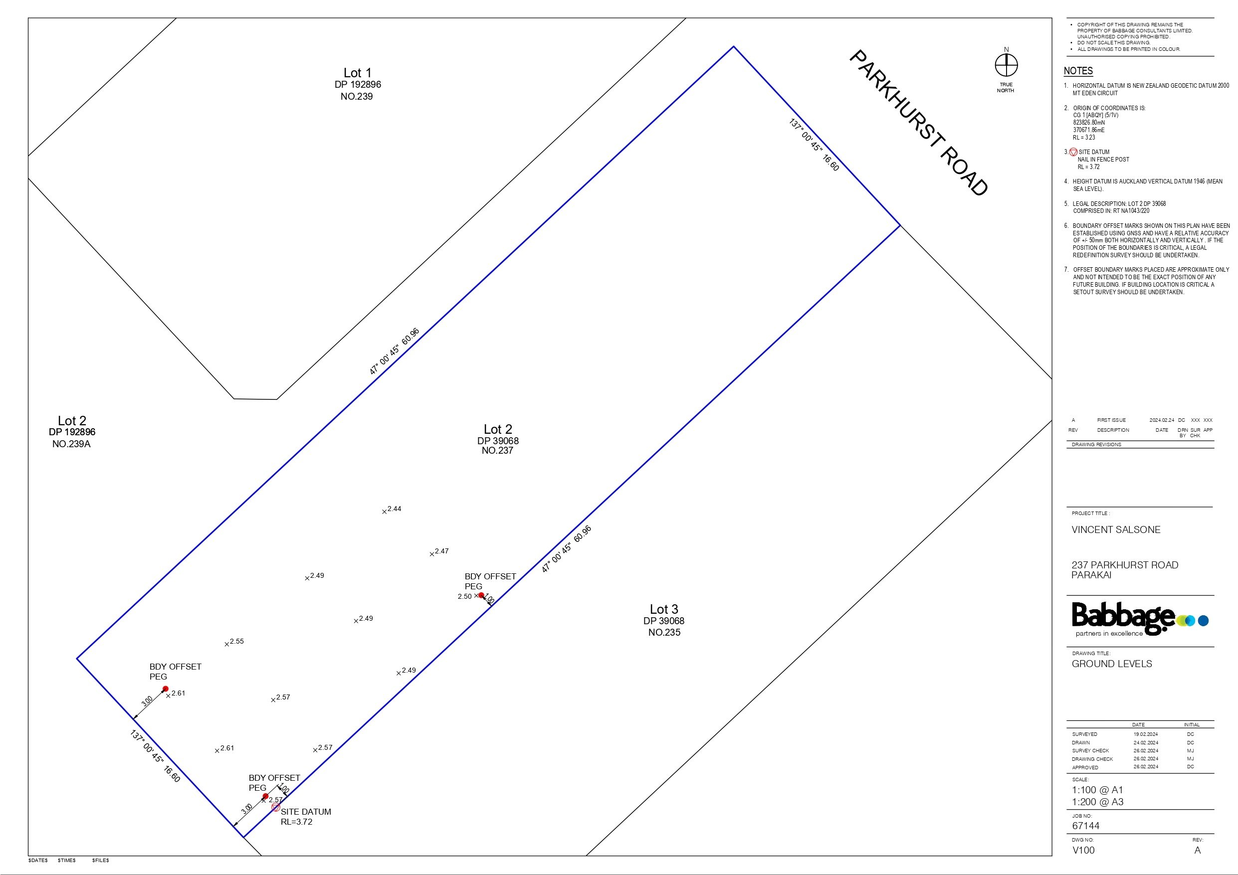
Thanks Ross Firstly, yes I agree, most projects will require a survey done and that takes the responsibility out of our hands hence getting Babbage out. We needed the minimum F.F.L. set on site so asked if he could take some levels around the building platform. Thanks for your message, great info in there for me to work through. Even when I don't include the spot levels the generated model contours are still not the same as my source information so is causing no end of confusion. The site is basically flat I but wanted to still set up a 3D model view for the client to have a look including a sun study. I have since set up an imaginary site with a steeper gradient to see if I could figure out the levels (which I obviously haven't as yet). I still need to learn about the ins and outs of site modelling so ISSUE 2 is a bit out of my depth at present as I have only just started using the program. I understand the concept of stories and why we use them but still don't understand why we cant use a datum or set point where the site model can relate to the finished floor level from the design layer. I am using stories and set my proposed F.F.L to the R.L of 3.72, which is the minimum requirement from the flood report, I can't see why this would not work with the contours set on the site model. I can basically grasp that the site model does not have an elevation as such(???) but need to understand how these CAN work together. I have now become a Pro Member so I can access Jonathan's teachings and have a site modeling webinar due next week so hopefully I will have more understanding after this. Thanks for your help Mon
-

Creating a viewport from design layers
Monique Freese replied to Monique Freese's topic in Architecture
Thanks I will have a look at the section viewport as an option. Mon -
Just looked at my GIS Council source data and the contour I have circled is supposed to be there it must have picked up the line somehow from the imported layer when I was tracing???
-
Site modeling - contour lines not showing in 2D top plan?
Monique Freese replied to Monique Freese's topic in Architecture
I still do not understand what is happening or how everything works mainly around setting the Z values or datum/elevation levels. I have posted another question on the forum with more information. Thanks so much for your input thus far. M -
Creating a viewport from design layers
Monique Freese replied to Monique Freese's topic in Architecture
Hi Yes I am using a 2D rectangle when attempting to crop the design layer view. Ta Mon -
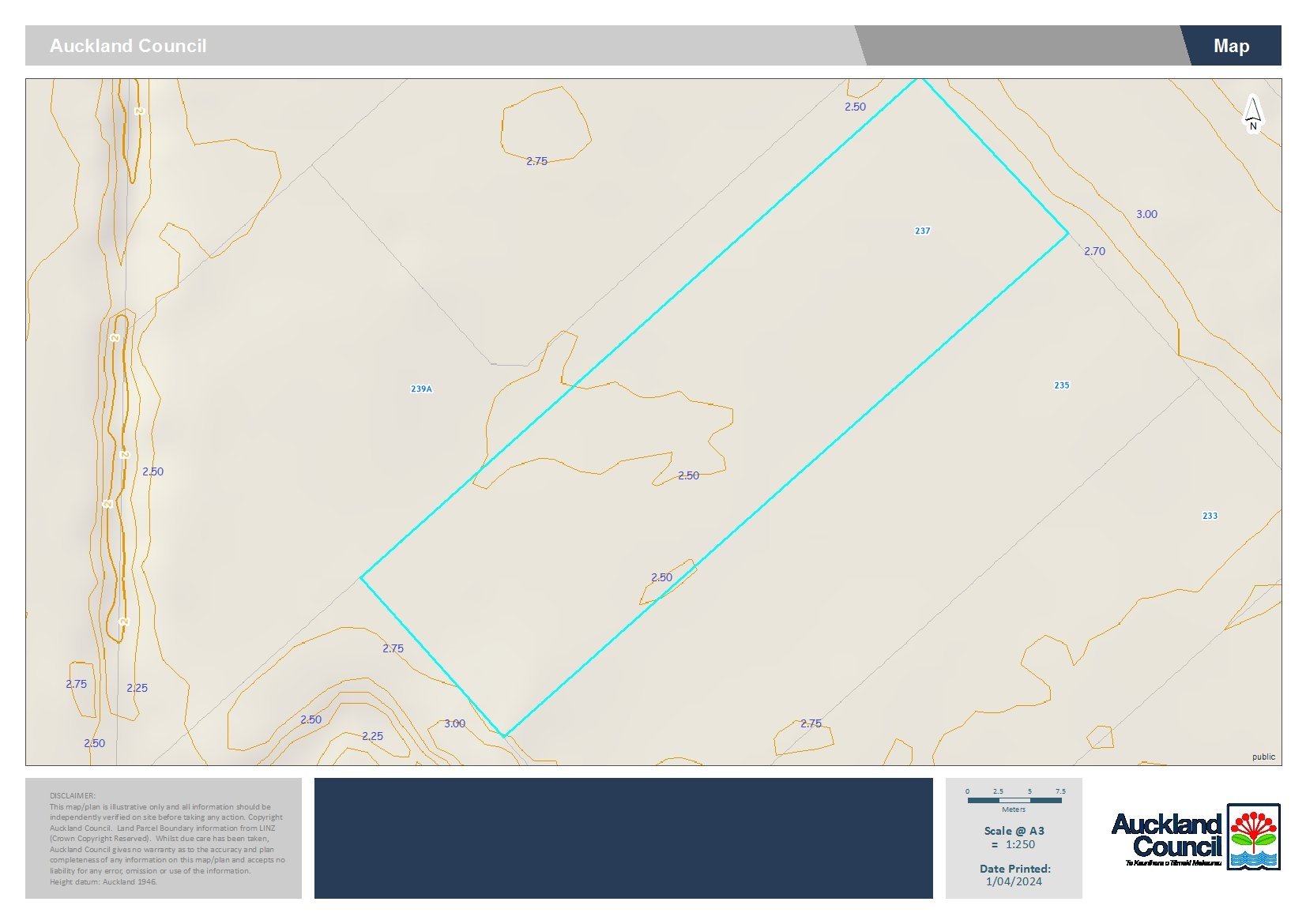
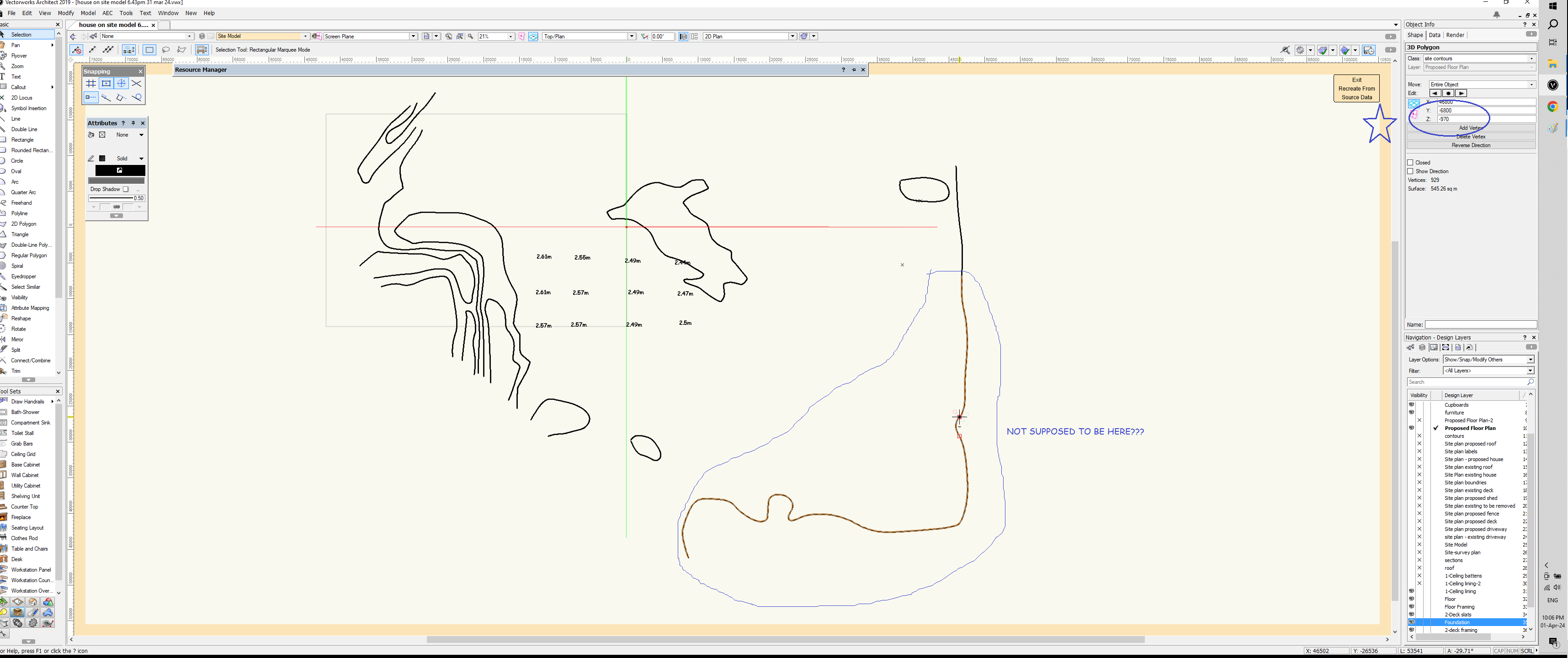
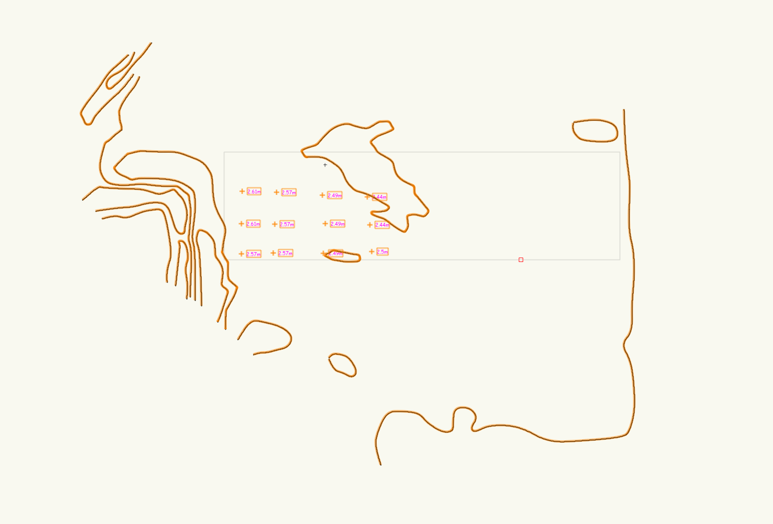
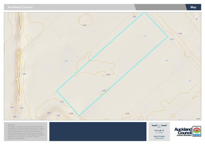
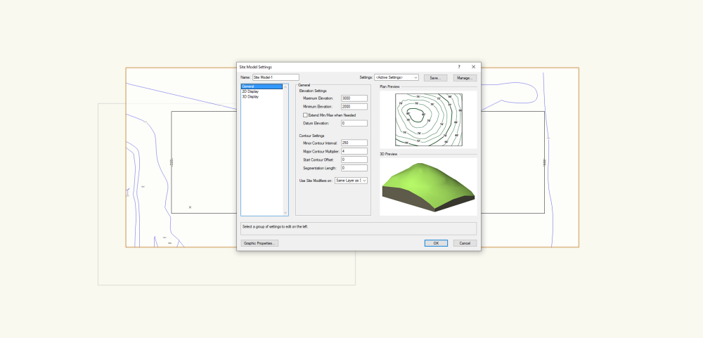
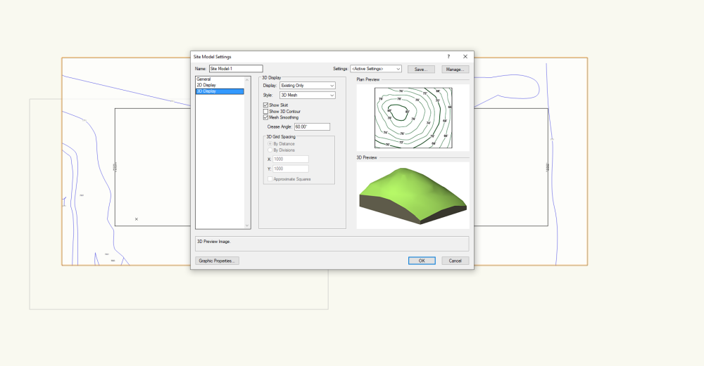
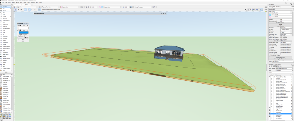
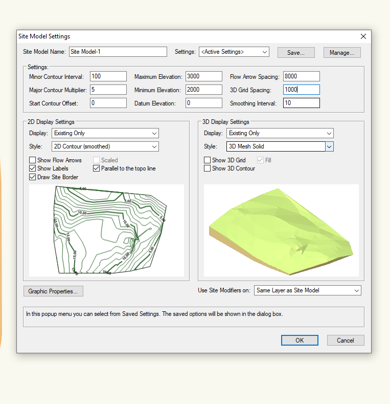
Hello ISSUE ONE I have input my survey info and ensured the contour lines are recognized as 3D polys, all the levels associated with each contour line is correct. The site does not have much fall, pretty much dead flat but I would like to show the basic contours on my site plan. I have used the contours from the Council GIS maps as source data and traced them, and also spot levels supplied by the surveyor - it would be great if the contours were uniformly rising as they would be easier for the program to create the model, but that is not the case. I created the site model and in 2D the contours are all skewed. I would ideally like it to present the same as the GIS layout. ISSUE TWO I can't seem to work out how to set the datum or elevation height on my site model so it corresponds to my house levels. I understand that Z is my height value and I have input the correct contour values and design layer elevational values for the building via stories, how do I get everything to relate to the site model? I have the site model on its own design layer and set the design layer elevation to 0, is this correct? What does the design layer elevation actually relate to? The lowest contour I have input is 2.00m and the highest 3.0m as per the GIS map and my house floor level (supported on poles) is 3.72m. On the site model settings under general the following: In the object info under site model the Geo Lowest Z is set to 2000 ..... is this correct? ISSUE THREE When in flyover mode looking at the following: 1. What do the red lines represent? - lowest and highest contour? 2. I have the skirt mode on so what defines the depth of the skirt? - the lowest contour or the datum set at 0 on the site model general settings..... I have just gone into the recreate from source data and have found this: The portion of contour I have circled is not supposed to be there? The Z values are incorrect, aren't they supposed to relate the the contour values I have input?? PLEASE HELP!!


-
Hello all I am trying to set up an elevations drawing sheet for my proposed house. I activate the desired design layers of my proposed house and place in an orthogonal view showing the north west elevation. I would like to crop the view so the viewport will only take the information I choose. I have watched instructional videos and read the help section. The viewport dialogue box comes up immediately but not the alert box* asking if I wish to use the cropped area as the viewport. If I continue and fill in the info in the viewport dialogue box and click ok it moves the hole view onto my elevation sheet, not the cropped view. *VECTERWORKS HELP An alert dialog box asks whether the object should be used as the viewport’s crop. Click Yes (also select Always do the selected action to always use a selected 2D object as a crop object when creating viewports). This alert box does not come up on my screen. What am I missing? Thanks Mon
-
Site modeling - contour lines not showing in 2D top plan?
Monique Freese replied to Monique Freese's topic in Architecture
It is turned on ........ sorry this all a bit new to me still. I thought the graphic attributes on the site model settings would be the classes for the contours. Also now realising how all the RL's relate to the ground plane so have to now ensure everything is set correctly so the site model is in the correct place on the Z plane. -
Site modeling - contour lines not showing in 2D top plan?
Monique Freese replied to Monique Freese's topic in Architecture
Have found the class under SITE-Contours -
Site modeling - contour lines not showing in 2D top plan?
Monique Freese replied to Monique Freese's topic in Architecture
The site model is on the NONE class -
Site modeling - contour lines not showing in 2D top plan?
Monique Freese replied to Monique Freese's topic in Architecture
The graphic properties come up from the site model settings box with all the different colours and line weights for contour major and minor but there does not appear to be a class for them showing in the classes tab in the organization palette..... -
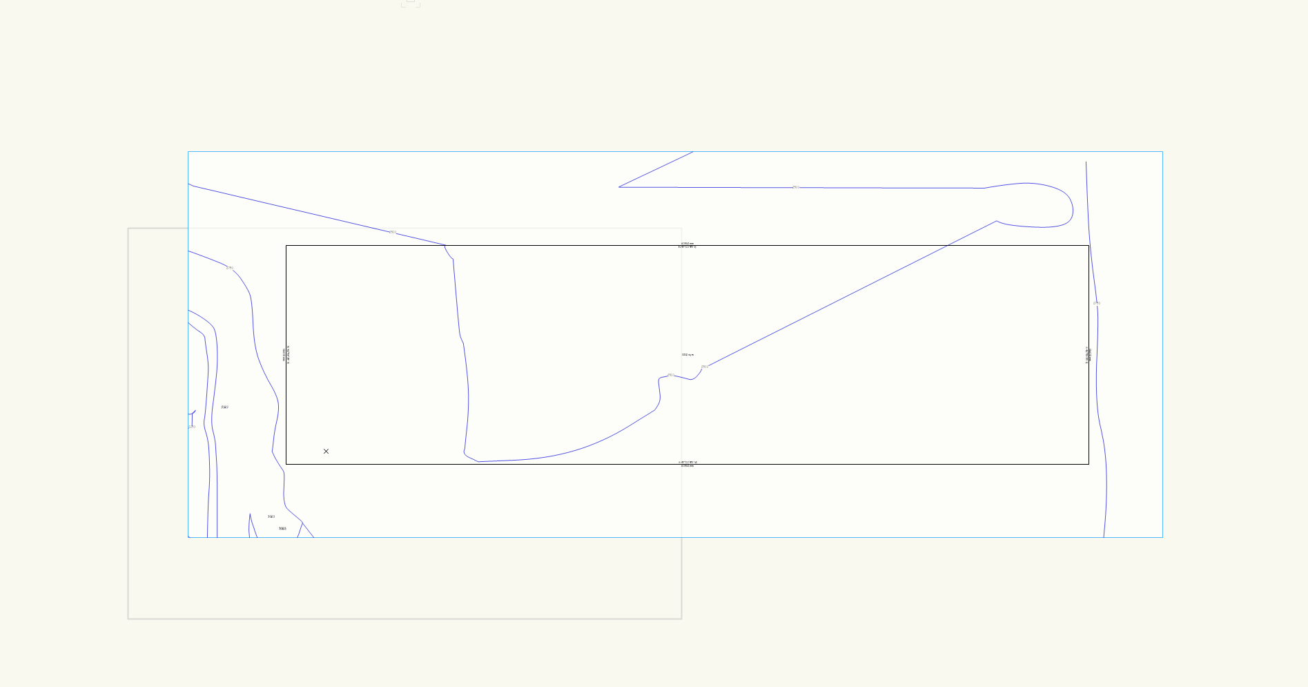
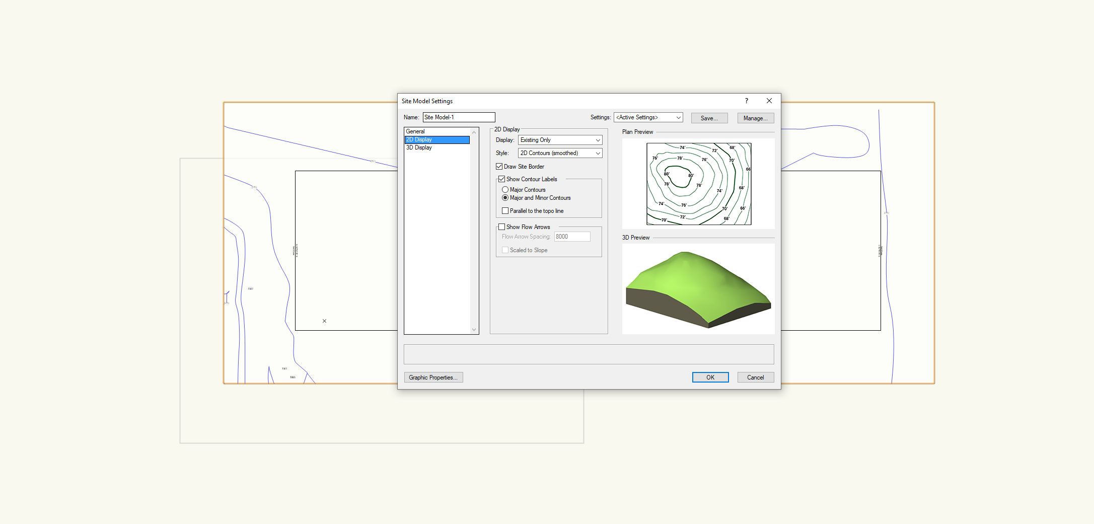
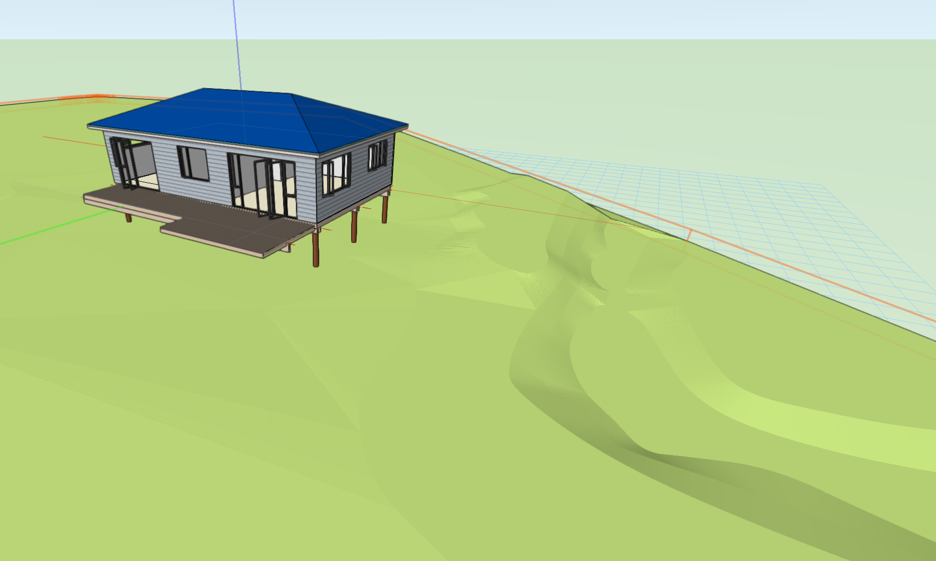
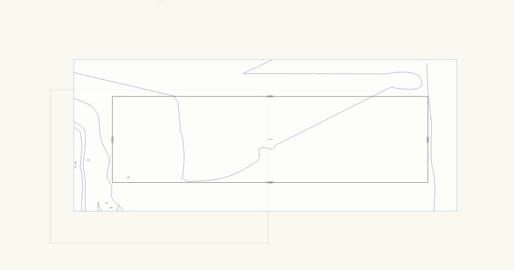
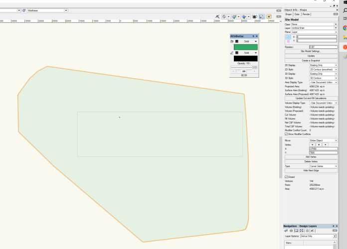
Hello me again Tom lol!!!! 😖 I am now working on the site model to hopefully produce a 2D contour plan and then position the proposed house (have used stories and story levels for all design layers etc) there by seeing it when doing a flyover. I have created 2D polygon lines for the contours and converted to 3D and spot levels via the stake tool (first attachment). I have then selected everything and asked for a site model to be produced. The result shows me, in plan mode, the boundary my site property boundary line but no 2D contours with notes. I have attached the settings I have chosen and the result in 2D plan mode and top Orth Open GL mode, in the latter you can see it has processed the info ok but not showing me any contour lines. When rendering in GL it looks really cool!!! I assumed the relative level of the ground would relate the the proposed finished floor level but it does not appear to be the case, how can I ensure the are relating to each other. The site model appears to relate tot the ground plane (the blue grid)??? I have changed the site model Z position so it looks semi correct but need to figure it out, is it the elevation datum on the site model settings? Ok that's it for now. Thanks Mon


-
Floor framing using AEC framing option
Monique Freese replied to Monique Freese's topic in Architecture
Yes Tom you are AMAZING and thank you so much for helping me. I figured out the following was causing the issues yesterday: 1. My laptop was playing up and not performing basic functions but gave no indication it was struggling so the actions I asked for were not being performed in a timely manner. So rebooted the laptop and HEY PRESTO things started working as they should. So after filling in the info and tapping OK I was able to click for start and end indicating the orientation of the joists. YIPPEE!! 2. When I looked at the joist properties I had ticked the SOLID option because I assumed it would then draw me a solid looking piece of timber in 2D plan view and 3D perspective , but alas no, only in 3D. I changed it to each of the settings so I could see what happened and NONE was the best option for what I wanted. 3. The batteries are starting to fail in my wireless keyboard so on occasion nothing was happening when I tapped a key ..... but strangely since I removed and reinserted the batteries there have been no further issues. Who would have thought all these would happen at the same time .... SIGH!! -
Floor framing using AEC framing option
Monique Freese replied to Monique Freese's topic in Architecture
Ok have found where it says the orientation of the joists but dont seem to get the dialogue box come up -
Hello I am trying to draw a floor framing plan and after watching multiple tutorials have chosen to use the AEC-framing option. I have indicated the perimeter of the floor and completed all the info required but there does not seem to be a question asking the direction of the floor joists? the program keeps drawing them along my building not across as I would like? Also in plan view the joists appear as a single line with a T end, I thought they would show as solid with the pen thickness around the perimeter and the colour I have chosen in the fill. Thanks Mon
-
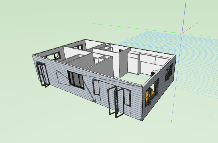
Tom You are awesome, I dragged out the front wall and you were correct, there was another wall underneath. The reason the middle window seemed to be correct is that the wall underneath also had the same window inserted so no wall in that area. Sometimes I get so frustrated not knowing what to do or how to fix seemingly very simple things .... sigh!!!! Big thanks Mon 😍
-
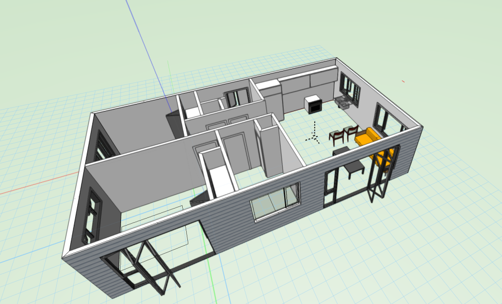
Hello all - new user here so I apologies for my simple questions. I have attached joinery to my walls using WinDoor, initially I copied and paste several of the units but realised they did not attach to the wall so finally figured out I needed to turn on the wall insertion mode, now all are showing as WinDoor in wall on the object info palate. When I render the building some of the joinery is correct and I can see through it to the inside of the building but some are showing the exterior wall cladding. How do I fix this?
-
Hello all I purchased the Vecterworks program years ago and kept updating until 2016 but have never really used the it until now as I was so busy it was still faster (in my mind) to draw by hand. I am finally forced to start using Vecterworks after beginning editing my hand drawings in PAINT and then PAINT.NET both not designed for our specific line of work. I am finally forcing myself to start using my Vecterworks program and am getting very frustrated as need to learn in a hurry to get my current projects underway in a timely manner. Is it ok to ask questions that would be very simple to an experienced user but totally frustrating to me as I cant find the answer??? I do attempt to search on Jonothan Pickup's channel with YOUTUBE (they are amazing) but sometimes there are little things that I just cant figure out. Question One I have started new file drawing a minor dwelling (a nice simple project to use to start) and have drawn the roof walls with some windows and plumbing fixtures etc. I have used some layers but did not know about story's when I started. I have also drawn a site plan, in another file, with existing house, proposed house, driveways decks etc all on the same design layer (I assume I can edit this). Can I combine the 2 files into one file so I can use the info of both to continue drawing? I have added design layers and story's onto the site plan file (spent a bit of time) so don't really want to repeat everything again in the proposed house drawing, there must be a way of combining the two. Please help ... this is taking up so much time,which I dont have allot of. Thanks for any help Mon