Jeff G
-
Posts
6 -
Joined
-
Last visited
-
That worked. Thank you
-
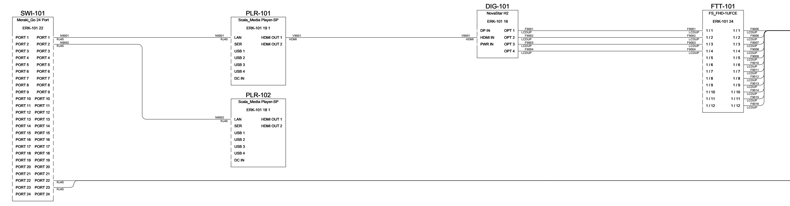
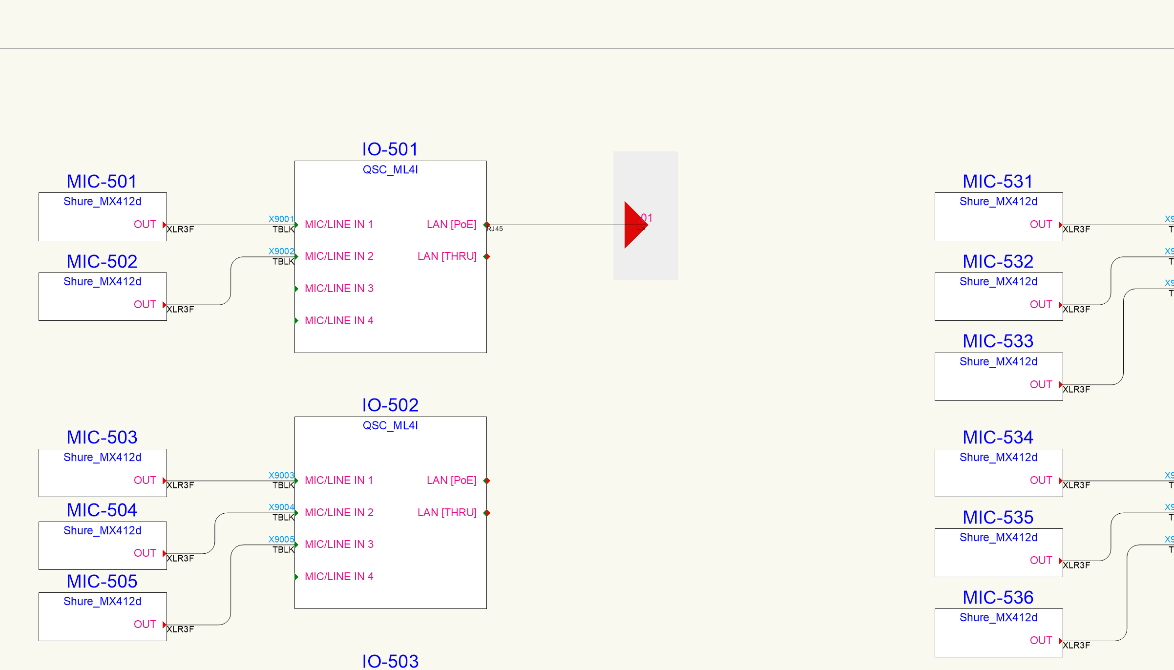
I like to publish my functional schematics in black and white. Whenever I publish, in and IO port symbols show up as gaps in the schematic block. Is there a way to fix or avoid this? I don't care if the port symbols are visible or not. Anyone have any thoughts?

-
It would be nice for connector panel IDs be able to coincide with drop point IDs. Usually we're specifying structural cable before drawing functional schematics and there are multiple cables that run from wall plates to a patchbay in the rack. Not all the cables are being used but they still need to be reflected as existing on the final drawing set.
-
Hi @Nikolay Zhelyazkov- I'm still having some issues with this and can't get things to scale correctly even after changing ConnectCAD settings. I uninstalled VW, reinstalled, created a fresh file, and the issue still came up without changing the grid or snap grid settings.
-
Working in VW 2024 with ConnectCAD and Spotlight. I'm having an issue with the size of my circuit blocks, specifically terminal panels and connector panels. They are all massive compared to the rest of the blocks. When I want to create a 48 port data patch panel, the spacing is very big and it doesn't fit within my drawing border. Anyone have any ideas how to fix this?

-
Jeff G joined the community
-
Hello all- I'm having some issues connecting a piece of equipment to a drop point. The cable route runs from the drop point and connects to a rack. When I try to connect the equipment object to the drop point, it does not show connection to the rack. Currently running Vectorworks 2024. I'm not sure if I'm even doing it correctly. Thanks in advance